
 Composite construction has contributed significantly to the dominance of steel frames in the commercial building sector worldwide.
Composite floors are usually incorporated into multi-storey commercial structures and typically consist of profiled steel decking with a reinforced concrete floor cast in-situ. The decking not only acts as a permanent shutter, but it also provides sufficient shear-bond with the concrete by means of the shear-studs, so that when the concrete has gained sufficient strength the two materials act ‘compositely’, hence it is known as a ‘composite floor’
The composite action is achieved by means of shear-studs which are welded through the decking to the top flange of the supporting steelwork by means of thro-deck welding. These shear studs provide sufficient shear connection between the concrete and the steel floor so that they act together structurally. Openings may be incorporated into the floor for stairways, elevator shafts, and service wells.
There are many benefits to be gained from this method of construction, some of which include:
Speed of construction
The individual decking sheets can easily be installed by hand. The use of the decking as a working platform speeds up the construction process for the trades that follow. Minimal reinforcement is required, and large areas of floor can be poured quickly.
Safety
The decking can provide a safe working platform and act as a safety ‘ceiling’ to protect workers below from falling objects.
Weight Saving
Composite construction is considerably stiffer and stronger than many other floor systems, so the weight and size of the primary structure can be reduced.
Structural stability
The decking can act as an effective lateral restraint for the beams, the metal decking may also be designed to act as a large floor diaphragm to redistribute wind loads in the construction stage, and the composite slab can act as a diaphragm in the completed structure.
Shallower construction
The stiffness and bending resistance of composite beams means that shallower floors can be achieved than in non-composite construction. This may lead to smaller storey heights, more room to accommodate services in a limited ceiling to floor zone, or more storeys for the same overall height. This is especially true for slim floor construction, whereby the beam depth is contained within the slab depth
Easy installation of services
Cable trays and pipes can be hung from attachments built into the dovetail profile. These hangers also allow for convenient installation of false ceilings and ventilation equipment.
Floor Plans and Layout of Decking
The layout and installation of composite decking is normally done by a specialist contractor and is a discipline separate from that of the conventional structural detailer. That being said, the steelwork supporting the deck is – and the framing plans should be prepared with the decking layout in mind.
We’ll first look at a typical decking plan. The information required by the decking contractor must include:
- Steel Framing plan, fully dimensioned, indicating the size and position of all structural members
- All floor openings for stair wells, elevator shafts, service ducts. Etc…
- The thickness and reinforcing details of the concrete slab together with the limits and edges formed by the decking
Though not the responsibility of the draftsman, all applicable loads and special requirements determined by the responsible engineer.
The decking plan itself is normally divided into bays, where a bay is the area to be laid from one bundle. Bays are usually designated by a diagonal line against which is written the number of sheets, the identification number for the bundle and the sheet length.
In addition, Further construction notes for the bay can be referenced using numbers in circles drawn on the diagonal lines. These references then refer to the general notes

The approximate starting point for laying the decking should be given on the drawings, together with the direction in which laying should proceed (shown here at the bottom left-hand corner) All supports (permanent or temporary) should be identified, and whether they should be in place prior to laying the decking.
The shear connector layout should also be indicated on the drawing, although in this example they have been omitted for clarity. The details of which including the size, type, and location relative to the steelwork and decking are usually provided as separate details – which we’ll look at later.
The location of all openings trimmed with steelwork, and all slab perimeters, should be given relative to the permanent supports. This is often in the form of a reference box titled with a reference number (for details shown elsewhere), the slab depth, and the distance from the edge of the slab to the center line of the nearest permanent support.
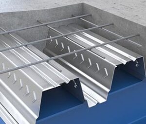
Decking Profiles
There are numerous decking profiles available which differ in width, length, thickness, shape, etc. from manufacturer to manufacturer, but generally they fall into 2 generic categories: Trapezoidal and Re-Entrant (Dovetail)
Stiffening ribs and embossments are built into the decking profiles – but these will vary according to the manufacturer. For details you will have to refer to the manufacturers literature.
The sheet thicknesses usually range between 0.9 and 1.2 mmm, any thicker may cause issues with the shear studs thro-deck welding – this would need to be verified by the equipment suppliers.
The width of the deck sheet is determined by the cover, which is the distance between the interlocks (where the sheets clip together). The interlocks are positioned so that when joined, the spacing of the ribs remains constant and uniform.
The depth (d) of the traditional shallow deck profiles range between 45 and 60 mm with a rib spacing of between 150 and 350 mm – these you would expect to span up to 3 m. without any additional propping.
Deeper profiles, up to 160 mm. are available which can span up to 4.5 m without additional propping.
Deep deck profiles, over 200 mm. deep are available – but these are used mainly in slim-deck construction – which is discussed in Composite Concrete Floors - Construction Details
For maximum spans of any particular decking profile, you will need to refer to the manufacturers literature and follow the guidance of the responsible engineer.
