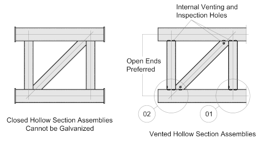
Frames and sub-assemblies such as trusses, girders and other pre-formed welded assemblies need special attention by the detailer to ensure that the assembly can be immersed and withdrawn from each stage in the process in a safe, efficient and effective manner. The pre-treatment solutions from the galvanizing process and the molten zinc must be able to flow freely into and around the assembly so that contact is made with all surfaces and all air is displaced. In turn, the liquids must then be able to flow out of and run off the part.
To achieve this, the assembly must be fabricated in a manner that each welded joint between the hollow section components must be properly vented to allow for the free flow of liquids and molten zinc both internally and externally.
Internal Vent Holes
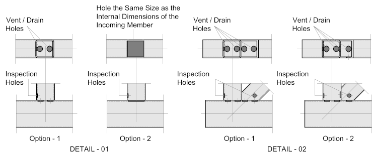
- Internal vent holes must be at least 50% of the connecting section. It is recommended they be the same size as the internal diameter of the connecting section where practical.
- Internal venting must be shown on shop detail drawings and be approved by the galvanizer prior to fabrication. The method of venting should be approved by the responsible engineer.
- Internal venting methods should be visible for inspection or be able to be otherwise proven to be satisfactorily formed.
- A min. Ø10mm external check hole must be included at each location where internal venting is specified on the shop detail drawings, allowing the galvanizer to safely proceed with dipping the article. These holes should be placed as close to the connection as possible.
DETAIL - 1 below shows two options for the placement of the vent and inspection holes:
Option -1- shows two holes whose area work out to 50% of the connecting section. They should be placed as close as practical to the inside faces to minimize any potential retention traps.
Option -2- which is probably better than Option 1, shows the vent hole cut out to the same size of the incoming section - this will virtually eliminate retention traps. However, it will be a more costly option and the welding will need to be of a high quality.
DETAIL - 2 shows a similar two options but with a diagonal member. In this case, the diagonal member is overlapping. If there is space, the drain holes are all confined to the chord member - however, should the overlap be substantial it may be necessary to provide a vent holes in the leg of the vertical brace member (Option - 2).
There should be an inspection hole at each joint

External Vent Holes
To ensure free flow of pre-treatment solutions and molten zinc together with the expulsion of air and gasses into and out of the assembly the ends of the main components should ideally be left open, where this is not an option external vent holes must be provided. These hole diameters are determined by at least 25% of the cross-sectional area of the incoming member.
For more information on this go to Galvanizing – Hollow Sections and Pipes

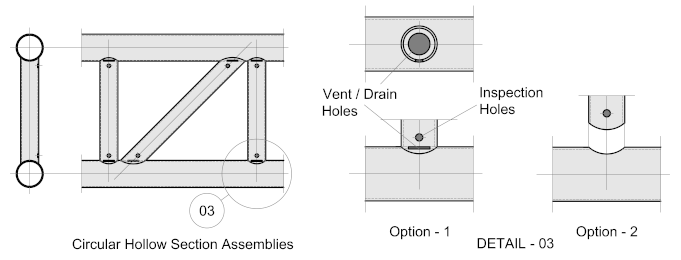
Circular Hollow Section Assemblies
Circular hollow sections offer the same options as above with a slight variation.
Generally, there is one vent hole at the connection whose area should equal 50% of the incoming member (Option - 1). Alternatively, the chord could be mitered opening up to the inside diameter of the incoming member (Option - 2).
The Pro's and Cons. of each option are as per rectangular hollow sections discussed above.

