In this example, we show an all-bolted Heavy girder truss. It may be formed from hot-rolled I or H sections
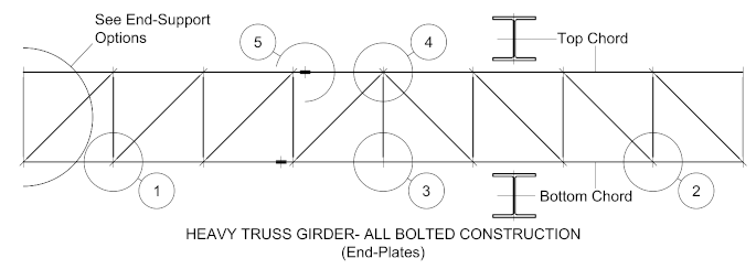
For all-bolted trusses formed using hot-rolled I and H sections, the work points are established from the geometric centers.

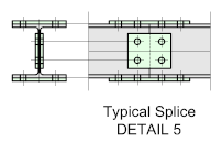
Splices should ideally be located so that they are staggered equally about a vertical truss member.
For more information on bolted splices go to: Bolted Beam Splices
End Support Options
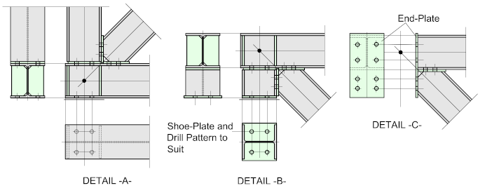
Below are some examples of typical truss support options:

Heavy duty truss girders are usually assumed to be moment resisting frames, so it's common practice to add web stiffeners to the supporting members.
For more information on this, go to:
Moment Resisting Frames
Stiffeners
Detail -A- illustrates a typical seating connection bolted through the bottom chord of the truss. The drill pattern for the bolts should align with the means of support.
Detail -B- shows a typical top chord seat. The leg length should be such as to allow sufficient clearance for the diagonal lacing member connection. The drill pattern for the bolts should align with the means of support.
Detail -C- shows a typical end-plate connection. For more on this, go to:
Moment Resisting Connections
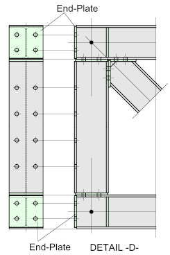
Detail -D- illustrates a fairly typical connection to a column. The vertical truss runs between the top and bottom chords.
The top and bottom chords are each fitted with and end-plate
The bolt-hole gauge should conform to the recommended or 'workable' gauge of the column
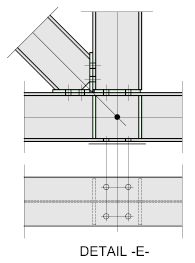
Detail -E- shows a typical connection for a cantilevered truss. The bottom chord is directly bolted to the support.
