
Floor Types
 Here, we’ll be looking at 3 floor types which represent most types likely to be encountered, they include:
-
- Down-hand Construction
- Integrated Constructions
- Slim-Floor Construction
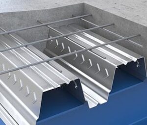
Down-Hand Construction
This is where the concrete floor sits on top of the supporting steelwork. The metal decking would typically span across multiple beams making it stiffer and stronger than over a single span with the joint placed at the center of the end supporting beam.
Shear studs are either thru-welded on site to the supporting beam, or the studs may be shop welded to the supporting beams while the decking is pre-drilled to match.
Integrated Construction
This is where the supporting steelwork is integrated into the floor slab. The decking is supported on shelf angles or secondary beams which are fixed to the web of the support beam below the top flange.
In this case, the decking will span between beams – the advantage is gained by the resultant overall lower depth profile of the floor.
Shear studs may be shop-welded to the beam web to provide a shear bond between the steel and concrete floor.
Slim Floor Construction
This is a relatively new advance in composite floor construction. The slim floor beam is an asymmetric profile where the bottom flange is wider than the top. It may be fabricated as a plate-girder, or may be a standard hot-rolled section with an additional flange plate welded to the underside of the bottom flange, or a standard section with the bottom flange cut away, replaced by a wider plate.
A standard range of asymmetric profiles are produced by Arcellor Mittal under the trade name of IFB profiles.
With slim floors the support beam is completely encased in the concrete floor. Deep decking is placed on the lower flange of the support beam which spans between beams.
The shear bond between the steel and concrete is achieved by dowels which are welded into the pre-drilled beam. Additional reinforcing is added into the trough of the decking, running the full length of the panel

Supporting the Deck - Bearing

When bearing on a steel beam using standard screwed of shot-fired fixings, there should be a minimum edge distance of 50 mm. This may also apply to reinforced concrete beams or columns.
However, good practice is to increase this value (For concrete and masonry supports) to 70 mm. with a minimum 50 mm from the edge to the fixing.
The examples above illustrate bearing distances for down-hand construction, but the principles will apply to all floor types.
We’ll now look at each floor type in turn.
Downhand Construction
This is where the concrete floor sits on top of the supporting steelwork. The metal decking would typically span across multiple beams making it stiffer and stronger than over a single span with the joint placed at the center of the end supporting beam.
Shear studs are either thru-welded on site to the supporting beam, or the studs may be shop welded to the supporting beams while the decking is pre-drilled to match.
A layer of fiber mesh is placed on top of the decking using spacers if necessary – all reinforcing must be in accordance with the responsible engineer’s recommendation

Joint Types
Ideally, the joints between panels should be placed at the center of the main supporting beam – it may be placed slightly off-center provided it meets the minimum Bearing Requirements.
There are basically two joint types – The Lap Joint and the Butt Joint
The Lap joint should be set out so that the lap is equal about the center of the supporting beam – the exception being if there is a shear stud welded to the beam – you may either offset the stud position or move the lap allowing the stud to be welded at the beam center. Whichever option is chosen; the stud should be placed on the underlapping panel.
Normally the lap is approximately 50 mm but this may vary according to the manufacturers recommendations.
A Butt joint will be placed at the beam center – the gap should be kept to a minimum allowing for normal fabrication tolerances.

Integrated Construction
Here the supporting steelwork is partially integrated into the floor slab. The decking is supported on shelf angles or secondary beams which are fixed to the web of the support beam below the top flange.
In this case, the decking will span between beams – the advantage is gained by the resultant overall lower depth profile of the floor.
Shear studs may be shop-welded to the beam web to provide a shear bond between the steel and concrete floor.
A layer of fiber mesh is placed above the support beam to provide continuity to the concrete. If deep decking is to be used, additional reinforcing may be placed in the trough.


All reinforcing must be in accordance with the responsible engineers recommendations.
Deck End Support
There are two basic cases at the interface of the decking with beams – where longitudinal end support is required and where side transverse support is required
In both cases a steel ‘shelf angle’ is normally detailed as the decking support, and it is preferable to fix this during fabrication. It’s important that the leg of the angle extends at least 50 mm beyond the flange of the beam to allow for fixing of the sheet to the steelwork
The support angles should be continuous and extend as close as is practical to beam connections, to minimize the unsupported length of the decking.
For Transverse deck support intermittent shelf angles may be used
Slim Floor Construction
This is a relatively new advance in composite floor construction. The slim floor beam is an asymmetric profile where the bottom flange is wider than the top. It may be fabricated as a plate-girder, or may be a standard hot-rolled section with an additional flange plate welded to the underside of the bottom flange, or a standard section with the bottom flange cut away, replaced by a wider plate.
A standard range of asymmetric profiles are produced by Arcellor Mittal under the trade name of IFB profiles.
With slim floors the support beam is completely encased in the concrete floor. Deep decking is placed on the lower flange of the support beam which spans between beams.

The shear bond between the steel and concrete is achieved by dowels which are welded into the pre-drilled beam. Additional reinforcing is added into the trough of the decking, running the full length of the panel.
Support is also required when the decking interfaces with a concrete wall.
This may be provided by attaching a steel angle, flashing, or timber batten to the wall, preferably by using cast-in fixings which are set into the concrete as the slip-forming progresses.
Provision may need to be made to achieve reinforcement continuity between the wall and slab – this can be achieved by drilling reinforcement bars into the wall and sealing with chemical resin grout.
Edge Trims and Cantilevers
The edges of the floor are usually formed using ‘edge trims’ made from pressed strips of light gauge galvanized steel. The depth (d) represents the depth of the concrete slab, while the width is determined by the required overhang. Most manufacturers have standard sizes – but will, in most cases, supply to any required dimensions.
Edge trim is normally delivered to site in standard 3.0 m long strips and cut to suit on site. The thickness of the steel used may vary with location, but is normally no more than 2 mm.
Nominal cantilevers can be achieved using the standard edge trims without the need for additional reinforcing – but this is usually limited to no more than 200 mm. when measured from the center-line of the supporting beam. Reinforcing may still be required depending on the loads to be carried at the edge. This must be determined by the responsible engineer.

Larger cantilevers (up to 600 mm.) means that the concrete must be designed as a reinforced concrete slab with the requisite additional reinforcing. This usually takes the form of ‘U’ bars extended over two supporting beams. (This must be specified by the responsible engineer)

When the cantilever is transverse to the supporting beam, this is fairly straightforward, but the decking will not overhang the support steelwork when it’s placed parallel to the supports. In such cases it’s necessary to add additional cantilever frames – this should be done on the framing plan.
Apart from the edge trim, it may be necessary to include closure plates in the decking to prevent any spillage of the concrete. Closure plates exactly mirror the decking profile and are available in standard lengths from the supplier.
Openings
Openings may be categorized by their size:
Small - openings up to 300 mm square - unlikely to present a problem structurally and does not normally require additional reinforcement.
Medium - openings between 300 mm and 700 mm square – normally require additional reinforcement to be placed in the slab. This is also the case if the openings are placed close together.
Large - openings greater than 700 mm square - should be trimmed with additional; permanent steelwork back to the support beams.

For small and medium size openings, normal practice is for the Main Contractor to form an opening by ‘boxing-out’ an area of decking using timber or dense polystyrene inserts before concreting.
The decking should not be cut until the concrete has gained sufficient strength then it may be cut away to form the opening, and the cut edges bent up or ground off.
If cutting the deck prior to pouring the concrete is unavoidable, temporary propping is likely to be required.
The need for additional reinforcement in the slab, or additional trimming steelwork, depends on the size of the opening. Requirements should be determined by the responsible engineer,
The drawings should clearly indicate what reinforcement is required around medium sized openings. This often takes the form of bars placed in the troughs of the decking adjacent to the opening, with additional transverse bars used to distribute the load transfer around the opening
For large openings, the supporting trimming steel should be in positioned prior to placing the decking. The opening should then be trimmed prior to casting the slab,

Trimming the Deck Around Columns
Often, columns will pass through the concrete slab meaning that the decking must be prepared to prevent the egress of concrete during pouring.
If the column is restrained with beams, then flashing plates (Cut as close as possible to the column inner profiles) can be placed sitting on the beams and fixed using self-drilling screws or shot-fixings.
On particularly large columns, it may be necessary to add extra support to the flashing plate, particularly at the corners. This can be done by shop-welding additional plates to the flanges of the beams, thus extending the flange width.
For columns without any connecting beams, it will be necessary to shop-weld trimming steel to the column. In this instance, angles are welded to the flanges of the column with plates welded into the web.
Some manufacturers provide custom\m solutions to trimming around columns – so check with them first.
