Crane-Columns are a subject unto themselves, they differ from the more conventional column in that they must resist substantial dynamic forces generated by the movement of the crane. These loads include the mass of the crane-gantry itself together with its maximum load carrying capacity, additionally these loads must be factored for the impact of the load during lifting.
The lateral forces include the longitudinal movement of the crane along its rail and the impact forces generated at the ‘stop’. These stopping forces are usually estimated at full-speed, meaning they will be substantial. Aside from these longitudinal forces, there will be sideways lateral forces.

These forces are generated by the movement of the carriage across the crane-gantry which will also include some form of ‘stop’. As a consequence of these lateral loads it’s general practice to restrain the top-flange of the crane-gantry girder by some means of ‘Tie-Back’ or ‘Surge-Girder’ back to the building-column. Therefore, the design of the building and the crane gantry girder cannot be separated.
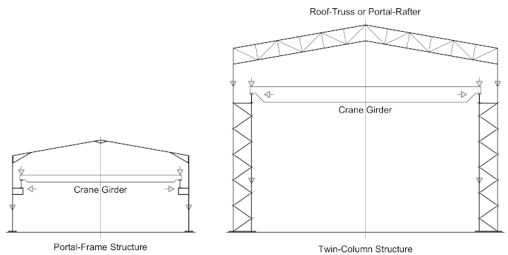
To complicate things further, due to the open nature of such buildings, there are no intermediate floors to tie the columns together thus reducing the effective-span, meaning that the structure itself must be designed as a ‘Portal-Structure’ with the roof-truss or portal rafter being the effective tie.
For Light-Duty cranes (less than 10 T capacity), a conventional Portal-Frame structure is often used, where the crane beam or girder is supported by a cantilevered ‘Corbel’ which may be either welded or bolted to the inside face of the column. For heavy-duty cranes, common practice is to use a ‘Twin-Column’ arrangement, where the crane-girder is supported from the cap of a supporting ‘Crane-Column’, while lateral stiffness is provided by the outer ‘Building-Column’.
Portal Frame Columns

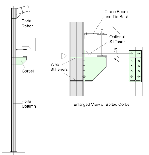
Conventional Portal-Frames are often used for Light-Duty applications (less than 10 T. capacity). The corbel is effectively a cantilevered bracket which may be either shop-welded or bolted to the column-flange. The crane-beam is seated onto the top of the bracket at a distance from the column sufficient to allow passage for the crane-gantry. As can be seen from the diagram, the eccentricity of the load will cause significant moment reactions at the joint which must be accommodated by the column flange, therefore it’s common practice to include stiffeners into the column adjacent to the top and bottom flanges of the bracket to resist the tension (top) and compression (bottom) forces, while the joint between the bracket and the column must resist the resultant shear.
The corbel itself is usually cut from a standard hot-rolled -I- section or, in certain circumstances may be fabricated from plate.
The top-flange of the crane-beam is usually restrained against the column by beams of a Tie-Back to prevent deformation of the top-flange.
Stepped Portal Column
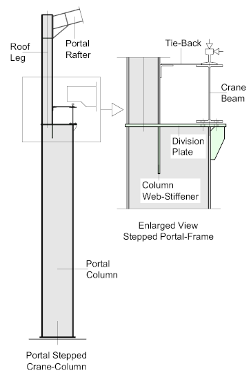
The second option for Portal-Frames is the ‘Stepped Portal-Column’ which is capable of much heavier loads and wider spans. The geometry between the wider lower portion and the roof-leg is determined by the required clearance between the crane-gantry and the roof-leg. The roof-leg is welded to the division-plate forming the cap of the lower section which must be faced for bearing. A web stiffener is welded to the web of the lower section adjacent to the flange of the roof-leg. The designer may wish this stiffener to be continuous, that is to say a slot may need to be cut into the web and welded all-round after fitment.
The web of the crane-beam should sit immediately above the inner flange of the column. The division-plate will need to be extended to accommodate the bottom flange of the crane-beam and be provided with slotted holes for lateral adjustment.
The stepped column is a very effective support method and can be used for cranes with a capacity of up to 50 T. but unfortunately can be rather costly, especially if the lower (wider) section is to be fabricated
Tie-backs are looked at in detail under the heading Crane Girders

Twin Columns
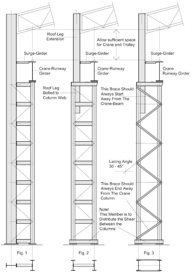
Twin columns arrangements are used for heavy-duty applications and are usually configured in one of 3-ways.
Twin-Leg columns are usually shop-fabricated and erected as a unit, they may be either bolted or welded, but welding is the most common form of construction. Their height is limited by the transport restrictions.
In each case, sufficient space must be allowed for the crane and carriage, complete with the lifting mechanism to traverse laterally and longitudinally along the length of the building.
The Crane-Girder must be restrained against the column or roof-leg by means of a plate or Latticed Surge-Girder
As a general rule-of-thumb, the horizontal center-distance between the columns should be somewhere in the range of the column-height (measured to the top of the crane-girder) divided by 7 (or multiplied by 0.15)

Fig 1 – Illustrates a simple twin-leg crane-column whereby the outer column is continuous, extending to support the roof truss or rafter. The columns are battened together at their center-line, sometimes with additional bracing. This configuration is similar to a more conventional stepped column and can be found for cranes with a capacity of up to 50 T. There is sometimes a height restriction with this configuration, where the total height is usually limited to around 15 m.
Fig’s 2 and 3 – illustrate typical configurations for heavy-duty cranes with a capacity of over 50 T. they may be latticed, as indicated in Fig 2 – or Laced as in Fig 3. The lacing on the battened columns is optional.
The columns are oriented so that the flanges face longitudinally along the building with the inside column supporting the crane-girder, while the outer column provides lateral restraint to the structure as a whole. The roof-leg, which is bolted to the inside web of the outer column is extended to support the roof truss or rafter.
For Laced-Columns – the bracing should be at an angle of between 30 and 45° which will be determined by the configuration of the bracing members as orientated according to the illustration (above). If the column flanges are relatively narrow, it may be necessary to offset the common work-points, which will introduce some eccentricity, but this is rarely a problem, if in doubt – check with the responsible engineer.
At the base of the columns, a horizontal Tie should be introduced to distribute the horizontal shear between the columns, usually this would be in the form of channels welded above the base-plates.
The Crane-Girder should be restrained against the roof-leg.
