There are two welding symbols in common use – American Welding Society (AWS) which until 1992 was the general standard – then ISO presented ISO 2553 which has largely been adopted by the EU and affiliate countries.
The Basic ISO Welding Symbol
The basic weld symbol comprises of:
- The full reference line
- The dashed reference line
- The Arrow line
- The weld symbol
- The Tail
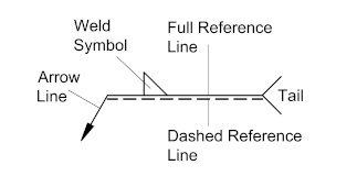
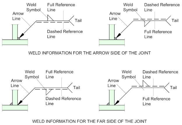
Weld symbols on the full reference line relates to welds on the arrow side of the plate being welded. Weld symbols on the dashed line relates to weld on the far side of the plate. If the welds are symmetrical on both sides of the plate the dashed line is omitted.
If the dashed line is above the full line, then the symbol for the nearside weld is drawn below the reference line and the symbol for the far side weld is above the dashed line
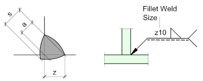
Fillet Weld Sizing
With the ISO system, the weld size is placed to the left of the weld symbol and is preceded by the letters: (z) / (a) / or (s) depending on whether the leg length or throat thickness is to be specified. Unless otherwise instructed, it is usually the leg length that is specified, in which case only the (z) box needs to be added. If the throat thickness is to be specified, only the (a) box needs to be added.
(s) refers to the effective throat thickness for deep penetration welds and is placed in front of the throat thickness dimension (a).
Therefore, if the effective throat thickness (s) is to be specified, both (a) and (s) values need to be added
z = Leg Length
a = Throat thickness
s = Effective throat thickness - for deep penetration welds
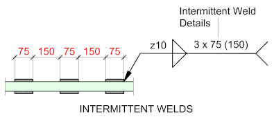
Intermittent Welds
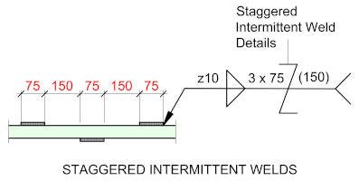
Intermittent welds are given in order of the number of welds x the weld length x the spacing between welds (Given in brackets) e.g. 3 x 75 (150)
If the number of welds are either not known, or not necessary, simply leave blank e.g.- 75 (150)
(Note that the dimensions to the welds are for reference only – it’s not necessary to dimension on the drawing)
Staggered Intermittent Welds
Staggered intermittent welds are given with the staggered Z symbol. In front of the symbol place the number of welds followed by the weld length - after the symbol, place the spacing between welds (In brackets) 3 x 75 / (150)
Again, If the number of welds are either not known, or not necessary, simply leave blank e.g. - 75 / (150)
Adding Supplementary Symbols
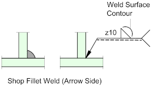
Supplementary symbols include the weld surface contours, surface finish. They will also dictate whether the weld is to be made in the workshop or on site.
In this example the weld is shown to be a single fillet weld with a convex contour.
For more information on Supplementary Weld Symbols see Butt, Tee and Other Welds with Basic Weld Symbols
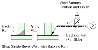
The next example, the weld is shown to be a single Bevel weld with a backing run on the far side.
It shows that the bevel weld is to be ground flush with the plate.
The bevel weld is a ‘Prepared’ weld, in which case the root gap and root face should be specified. These dimensions are set out in ISO 2553 – or they may be detailed by the detailer, with a reference to the detail given at the tail of the weld symbol.
For further information on this go to Weld Preparations.
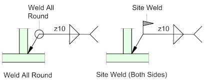
The Site Weld in indicated by the flag at the junction of the reference and arrow lines.
The Weld All Round (Peripheral) is indicated by a circle at the same junction - this would indicate the parts are to be Shop-Welded
These symbols may be combined to indicate an all-round weld on-site.
The Tail
In the tail, ISO recommends placing the welding process reference and the Weld Class.
The Welding Process refers to the manner in which the weld, (e.g. Arc welding / ERW welding etc.) is to be placed and are in the form of a numeric code as specified by EN ISO 4063. (See Table Below)
The Weld Class refers to the quality of the weld which are designated B / C / and D.
This is a list of welding processes, separated into their respective categories. The associated N reference numbers are specified in ISO 4063 (in the European Union published as EN ISO 4063)
| Description | N | Characteristics | Application |
| Flux Cored Arc Welding | 136
137 |
Continuous consumable electrode filled with flux | Industry, construction |
| Gas Metal Arc Welding | 131
135 |
Continuous consumable electrode and shielding gas | Industry |
| Gas Tungsten Arc Welding | 141 | Non-consumable electrode, slow, high quality welds | Aerospace, Construction (piping), Tool and Die |
| Plasma Arc Welding | 15 | Non-consumable electrode, constricted arc | Tubing, instrumentation |
| Shielded Metal Arc Welding | 111 | Consumable electrode covered in flux, can weld any metal as long as they have the right electrode | Construction, outdoors, maintenance |
| Submerged Arc Welding | 121 | Automatic, arc submerged in granular flux | |
| Magnetically Impelled Arc Butt Welding | 185 | Both tube ends are electrodes; no protection gas; arc rotates fast along edge by applied magnetic field | Pipelines and tubes |

Very good information and knowledge. Thank you