Fabricated box-girders are used for extra-long span, high load applications such as bridges, stadiums, and other such high density public access areas. Their aesthetically pleasing appearance makes the popular for such applications due to the fact that there is no external visible stiffening or joints.
Box-girders may be formed to almost any shape, but most commonly in section, they are either square, rectangular, or trapezoidal. They may be tapered or curved along their length enabling the application of greater unsupported spans.
Materials
It’s now common practice to use corrosion-resistant ‘weathering steel’ in the construction of box-girders even though a specific coating system may be specified. In suitable environments weathering steel forms an adherent protective rust ‘patina’, that inhibits further corrosion.
The corrosion rate is so low that bridges fabricated from unpainted weathering steel can achieve a 120 year design life with only nominal maintenance. Hence, a well-detailed weathering steel bridge in an appropriate environment provides an attractive, very low maintenance, economic solution.
Such steel is marketed under the trade name ‘Corten’
Advantages and Disadvantages
Advantages
- Box-Girders offer a high resistance to torsion (twisting) when properly stiffened internally.
- The disposition of their elements (2 x Flange and 2 x Web-Plates) makes them suitable for long unsupported spans
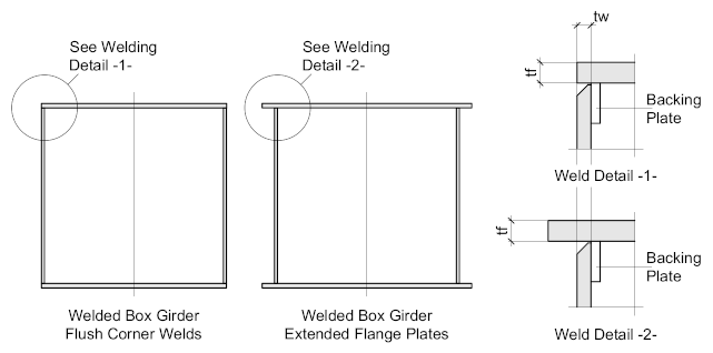
- Flush welded box-girders have few features that can accumulate dirt or moisture, therefore making them durable. Box-girders with extended flanges may accumulate contaminants on the lower flanges, but provided the welding is of a high quality the risk of crevice-corrosion can be contained.
- Box-Girders can present a pleasing appearance.
Disadvantages
- Fabrication costs can be high due to the necessity of some form of jig to hold the work in place during welding.
- Most welding needs to be manual due to the limited scope for ‘automatic’ welding’
- Access to the inside of the box-girder is often necessary to fit the internal stiffening and / or diaphragms bringing into play the ‘health and safety’ requirements for working in enclosed spaces.
- In-situ site-joints are not an option. Box-girder lengths must be fabricated and delivered to the longest manageable size and joined on site prior to erection. Such joints must be made to a high level of accuracy, often in a controlled environment.
Box Girder Construction
When fabricating box-girders the fabricator will usually form some sort of jig, to ensure the profile of the girder is maintained and that the component parts are held securely in position when welding. In all but the largest girders (over 1.5 x 1.5 metres) it should be assumed that all welding will be carried out from one side (outside) in which case, the plate ends should ideally be prepared.
Generally, the weld preparation would be a single bevel where the thinnest plate does not exceed 16 mm, above that, a double bevel may be required, which would require access from both sides (inside and outside). A single bevel weld may require the use of a backing plate, which would be shop-welded to the thickest plate (usually the flange) and ground flush at the mating face. The backing plate will assist the workshop in aligning the flange and web plates ensuring they form the required angle.

If a backing plate is not employed, it may be necessary to run a seal weld on the inside of the girder to prevent crevice corrosion. Internal corrosion is always a factor in box girders, as a consequence all welds are usually continuous and must be fully checked and signed off.
It should be noted here, that welding is critical to the performance of welded box-girders, what has been noted here should only be considered as a guideline for the draftsman. The weld design and specifications must accompany the engineer’s girder design.
Bridge Box Girders
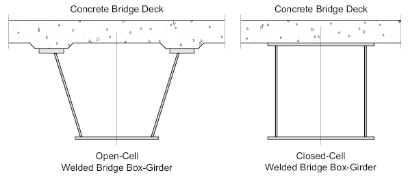
Bridge-Girders supporting a concrete bridge-deck are designed to be either Open-Cell or Closed-Cell.
Open-Cell Box-Girders
Are most commonly found on bridges where the top is closed by means of the concrete bridge deck, the concrete deck may be either pre-cast or cast in-situ, in which case a steel shutter deck will be fastened to the top of the box-girder to enable the placement of the steel reinforcing bars and pouring of the concrete.
Open-cell box-girders are inherently prone to buckling and distortion during fabrication, delivery, and erection until the deck- slab has been placed. Therefore it’s necessary to provide cross-bracing under the top flanges in order to maintain its profile. The bracing should not interfere with the deck construction.
Ideally, open-cell bridge girders should be horizontal with a uniform depth, but for longer spans, a variable-depth girder may be necessary. With trapezoidal sections, this means the profile will change over the length of the girder resulting in a variation of the width of the bottom flange, complicating its design and fabrication.
Also, long-span - variable depth box-girders invariably need to be erected in position in one heavy lift which can only be achieved using specialist equipment under expert supervision.

Closed-Cell Box-Girders
Are fully enclosed with top and bottom flange plates. The flange plates may be either flush with the web plates, or extended to facilitate lining up and welding.
To facilitate the erection of box-girders, properly designed and located ‘lifting-lugs’ must be provided. Most collapses occur during erection.
Stiffening a Box Girder
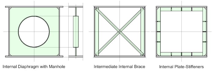
A box girder must be stiffened (usually internally) to resist the forces acting upon it, and to ensure the girder maintains its shape profile. There are three commonly applied stiffening alternatives:
A Solid Diaphragm
Which is welded to the inside girder plates, such diaphragms are usually provided with a manhole to allow access inside the girder for inspection purposes. If a manhole is provided it should not be less than 600 mm diameter (typical manhole) and should be surrounded with a flange ring. As a rule-of-thumb the size and thickness of the flange ring should be such that its volume is equal to that of the material removed to form the hole.
Intermediate Braced Stiffening
Is really employed to maintain the shape profile of the girder, its often used as a temporary measure when transporting the component lengths to site for final assembly. If left in place it may inhibit internal access for inspection and maintenance purposes.
Internal Plate stiffeners
Are welded transversely and longitudinally to the inside of the girder plates at centers determined by the engineer. Such stiffeners act as reinforcing for the flange and web-plates and are often used in conjunction with the solid diaphragms to act as intermediate stiffeners.

Bearing/Seating Positions
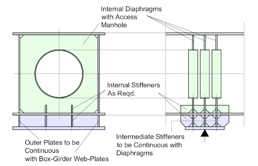
Often a box girder will require a bearing pad where it sits on a vertical support. generally, the principle at bearing positions is that the load should be immediately transferred to the vertical web plates while internal stiffening is provided to assist with the load distribution.
The bearing position may be located anywhere along the length of the girder according to the design. As bearing details will vary widely according to the application - the sketch below should be seen as typical to illustrate the genera; principals
The detailer should have few decisions to make with such girders - the design and guidance from the responsible engineer with regards to stiffening, welding and all applicable standards and specifications.
Care must be taken to ensure the girder can be erected in position carefully and accurately - lifting lugs must be designed and positioned to ensure safe handling of the girder during lifting. Most collapses occur during erection

