A moment connection is designed to resist rotation at the joint - most hollow section connections, unlike open section connections, will not allow a great deal of flexibility and will rely on the rotation capacity of the connection components of the incoming beam. These connections are defined specifically as Moment Resisting which means the load transference between the beam and column takes it's path through the sidewall of the hollow section columns.
The following connection examples represent some of the more common connection types:
Typical Examples
Side Plate Connections
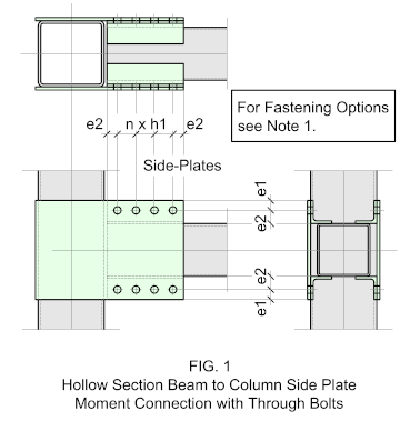
Fig. 1 illustrates a typical side plate connection which will accommodate any width of beam provided it is less than the column. The side plates may be welded to the column (as shown) or shop bolted using bling fixings. The incoming beam has angle cleats welded to the top and bottom faces which are Through-Bolted on erection. If the situation allows, the angle cleats may be substituted by Channel sections.
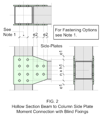
Fig. 2 shows a typical side plate connection using all blind fixings - to be most effective, the incoming beam should be the same width as the column.
Angle Cleat Connections
Angle Cleats are not often used for moment connections and when they are they are used for relatively low reactions. Also, they are not particularly visually appealing though they do offer the advantage of using Through-Bolts, making site erection much easier.
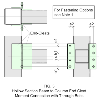
Fig. 3 shows a typical end-cleat connection with the cleats welded to both the column and incoming beam. As with the flexible version of these connections, end cleats will leave the end of the incoming beam open - this may be closed with a closure plate.
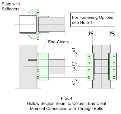
Fig. 4 shows a variation of the former with the column cleats replaced with a plate, which is then stiffened back to the column.
End-Plate Connections
End-Plate moment connections are the most widely used, they offer many advantages and will accommodate a wider variety of load combinations.
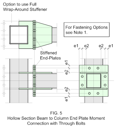
Fig. 1 shows a typical end-plate moment connection which allows for a 4-sided bolted connection offering greater resistance to the bending moment. In order to accommodate the top row of bolts, the column end-plate should protrude from the face and fixed to the column by means of horizontal plates welded to the outside faces. This connection requires a thick wall hollow section to be effective, or the plates may be extended to wrap around the entire column thereby guaranteeing a better distribution of the forces - this may allow the use of a thinner wall column. This will be determined by the responsible engineer.
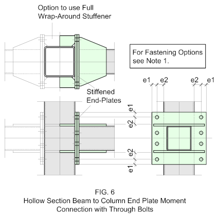
Another option is show in Fig. 6 where the plate is fastened directly to the column. This configuration will only allow for a double row of bolts and is more suited to a lighter duty. As with the former, the plate is fastened back to the column using partial (as indicated) or full wrap around stiffener pates welded to the outside faces of the column.
The incoming beam has a matching end-plate fitted wit horizontal stiffeners welded to the top and bottom faces.
As with all end-plate connections, the incoming beam end will be closed which, if galvanized after fabrication will need to have vent holes to allow for the ingress of the molten zinc and the expulsion of gasses.
For more information on this, go to Galvanizing.
Moment Connections with Open Section Beams
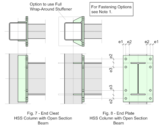
You will probably come across this connection type more than any other. there are two options commonly used. Fig. 7 shows a typical end-plate moment connection using a cleat welded to the column with the incoming beam connecting by means of an end-plate. Fig. 8 shows a similar arrangement with an end-plate welded directly to the column with stiffeners welded to the outside faces. The stiffeners may be partial (as indicated) or the full wrap around type.
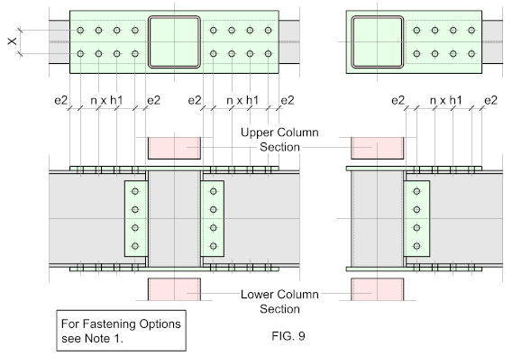
For those more familiar with moment connections Fig. 9 should be more recognizable. It's a heavy duty connections used mainly on larger sections - it can be costly to fabricate and erect but it's extremely effective when dealing with large moments.
It may be configured as single or double (as illustrated) and may be site welded of bolted. In all cases, the flange plates are continuous. The joint itseld is shop fabricated as a unit and fastened to the upper and lower columns on-site - it mat be either site welded of bolted, in which case to lower column must be fitted with a pre-drilled cap plate, while the upper column has a base-plate. This connection can also double up as a column splice, which can be very useful , particularly on large structures.
