The definition of a beam is; a horizontal member which spans between supports and supports loads at right-angles to the member. Almost any steel section can be classified as a beam provided it can be supported adequately and meets the duty requirements.
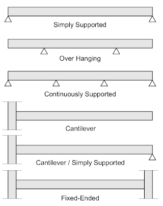
A beam is usually designated according to the manner in which it’s supported, which may be: Simply Supported, Over-Hanging, Continuously Supported, Cantilevered, or Fixed Ended.
Simply Supported
Simply supported beams are often referred to as ‘Pin-Ended’, the end connections are essentially flexible offering little or no restraint to end moments. Pin-Ended’ or Flexible Connections are dealt with in detail under their headings
Over-Hanging
Over-Hanging beams are essentially supported away from the beam ends with the over-hanging section essentially cantilevered. The connections are Seated and may be supported either from under the bottom flange or suspended from the top flange.
Continuously Supported
Continuously supported beams are supported from each end by means of Seating Connections while also being supported at intervals along its length, as with over-hanging beams, the intermediate supports may be either from under the bottom flange or suspended from the top flange.
Cantilever

Cantilever beams are connected at one end to either a vertical column or a horizontal beam by means of a Rigid, or Fixed, Moment Resisting Connection, while the free end is effectively unsupported.
Cantilever / Simply Supported
Cantilever / Simply Supported beams are connected at one end to either a vertical column or a horizontal beam by means of a Fixed or Moment Resisting Connection, while the free end is supported by means of a Flexible Connection. This is an unusual connection usually restricted to long cantilevered beams where the resulting end moment is excessive.
Fixed Ended
Fixed-Ended beams are supported by Moment Resisting Connections at each end and are the key stabilizing elements in Framed structures.
The horizontal component of the beam is the flange, while the vertical component is the web. Generally, the flange is designed to resist the bending moment while the web resists the shear component. The flange to which the load is applied, either top or bottom is designated the Compression flange while the opposite is the Tension flange. The most common beam shape is the –I- section which may be either a ‘standard’ hot rolled or fabricated section.

The -I- section is very efficient in bending due to the thickness of the flange and efficient in shear due to the thickness and depth of the web. However, the -I- section has a reduced capacity in the transverse direction (that is when the load is applied to the web) and is also inefficient in resisting torsion or twisting, therefore longer span beams need to be restrained laterally. Where this is not possible square or rectangular sections are preferred
Beams may be Standard Hot-Rolled or Fabricated.
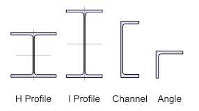
Hot-Rolled Sections include, I and H profiles together with Channels and Angles
Fabricated Sections include, Plate Girders, Box Girders, Castellated and Cellular Beams
