 The model is not just a pretty picture, it is in fact a digital representation of the completed structure and contains all the information necessary to fabricate, erect, plan and execute the entire project. This information includes all the mathematical and property data relating to the section profiles used, including all connections and their individual components down to every nut, bolt, hole and weld. It will also contain the information on how each component part is linked to another by means of geometric and dimensional constraints. In addition, the model will automatically look for and detect interferences and collisions between parts down to every bolt and check that these relationships are in accordance with pre-determined limits and settings. On the subject of settings, before you begin with the model, check out the Settings blog.
The model itself is fully Responsive. The grid, frame, connections, parts and bolts are all linked up and adapt when needed. When the grid is changed, the frame will adapt and when the frame changes the connections will adapt. This results not only in productivity gains during revisions, but presents opportunities for re-using some regularly drawn building components.
So when the model is changed or updated, the General Arrangement Drawings, Detail and Assembly Drawings, Bills of Material and NC Files automatically update.
The model will enable the automatic generation of:
- Workshop details
- Assembly details
- General arrangement drawings
- Bills of material (BOM’S)
- CNC NC file generation
- BIM (Building Information Modelling)
Let’s look at how the model creates and stores all this information:
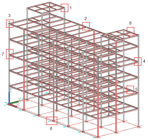
(See Connection options 1 to 8)
Mathematical Data
This would apply to the dimensional properties of the various sections and profiles which are contained in databases and stored in the Profile Libraries. With Parabuild, they include sections and profiles in accordance with standards from the EU, UK, US, Canada, Australia/NZ - in metric and inch units wherever applicable. Also included are profiles from Japan, China, Korea, Taiwan and numerous other far eastern countries. Section profiles include:
- Hot rolled sections
- Cold formed profiles
- Square, Rectangular and Circular hollow sections
- Flats, bars and rounds
- Open Grid and raised pattern flooring
The Parabuild profile libraries are fully customizable in that new profiles may be added including custom shapes and non-standard fabricated sections.
Property Data
The weights of profiles are combined in the profile databases, while materials, grades, specifications and finishes are determined by the Settings.
Constraints
When detailing a building many connections and parts will be repetitive, and often changes will be needed to the model. Therefore, it is important that your structural detailing solution offers a 3D model where the grid, members, parts and bolts are all linked and adapt to changes.
The solution is to use Geometric Constraints, which has been very successful in mechanical CAD but was never adopted in steel detailing. The reason for this is also obvious: there are thousands of geometries in a single structure and it would be too much work for a detailer to manually constrain all of them. Another challenge is for the software itself: calculating large constrained models like this takes a long time on mechanical CAD software.
Parabuild has introduced a new technology to meet these challenges. The performance problem has been solved by writing a proprietary geometric solver designed specifically for the structural sector. Manual constraining is only needed for detailers that wish to create custom connections and macros. Templates can be applied with ease in any 3D model, and Parabuild will take care of copying the constraints. Members and individual parts can be efficiently placed through the Context Modeller and will be automatically constrained.
Constructing the Model
There are basically two ways to construct the model:
Both of which are fully explained by hitting on the links.
Viewing the Model
The model , particularly if its a large one can become very 'busy' often making it difficult to identify particular objects. Here, the Visibility Manager can prove to be very useful.
Using this feature, it's possible to isolate or hide a selected level or row on either the X or Y axis. In addition you can hide or isolate any particular chosen object or objects.
Connections
Once the skeleton of the structure is completed its time to Connect everything together. With Parabuild its simply a matter of indicating the two members to be connected and selecting the required connection type – once done the connection will be immediately drawn accompanied by the Edit Dialog. Here you can edit the dimensions which in turn, will be immediately reflected on the drawing. If you are unsure about editing dimensions, then refer to the Best Practice Guidelines and proposed Standard dimensions for each connection type (See references at the bottom of this page)
At any time, you can return to the edit dialog by selecting the Review Macro button and selecting the Green Macro Sphere.
Connections can be copied to other parts of the structure using the Propagate or Smart Copy Macro commands.
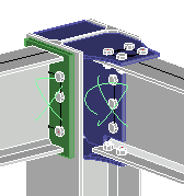
Connection Detail 1
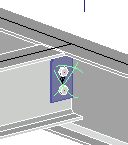
Connection Detail 2
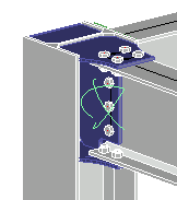
Connection Detail 3
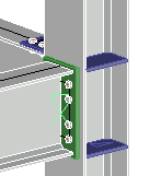
Connection Detail 4
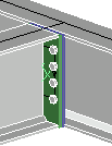
Connection Detail 5
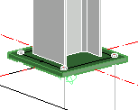
Connection Detail 6
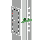
Connection Detail 7
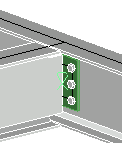
Connection Detail 8
Best Practice Guidelines for Connections
Connections, in general, will account for less than 5% of the total tonnage of the structure, but will account for as much as 35% of the fabrication costs – so any advantage gained here will have a significant effect on the financial viability of any project.
Connection Types
Connections can be loosely divided into 3 main groups:
- Flexible Connections (Also referred to as Simple or Shear Connections)
- Rigid and Semi-Rigid Moment Connections
- Seating Connections
Each of these groups contain the following:
Flexible Connections: (What are Flexible Connections?)
Flexible connections are the most common connection type likely to be encountered by the structural detailer - they will make up a great majority of beam-to-beam connections and on Braced Frame structures will account for most beam-to-column connections as well. However, common as these connection are, the engineer will rarely design of specify each connection - leaving it up to the fabricator / detailer to take on that responsibility.
To assist the detailer in understanding the advantages and disadvantages of these connections, we've prepared a Selection Guide for each connection type.
Moment Connections: (What are Moment Connections?)
- Site-Bolted End-Cleats
- Site-Bolted End-Plates
- Site-Bolted Flange-Plates
- Site-Bolted Moment-Trees
- Typical Site-Welded connections
Seating Connections: (What are Seating Connections?)
- Beam-to-Column
- Beam Parallel to Column
- Beam to Beam Crossover

