
What are Moment Connections?
REVISIONS TO PAGE
- Duplicated text removed
 At first glance, a moment-frame appears to be a simple post-and-beam construction
With a braced-frame these lateral forces are absorbed by the bracing system, which transmits those forces through the diagonal members, into the vertical columns, and into solid ground via the foundations.
The best way to explain a moment frame is to compare it to a Braced Frame.
With a braced-frame these lateral forces are absorbed by the bracing system, which transmits those forces through the diagonal members, into the vertical columns, and into solid ground via the foundations.
The bracing system itself, acts like a vertical truss, whereby the bracing members act in either tension or compression, depending on how its configured, while the horizontal beams and vertical columns act in compression. The connections between the beams and the columns are therefore designed to be ‘flexible’ and theoretically free to rotate, thereby not transmitting any significant moments into the column.

Consequently, the connections need only to be designed to resist vertical shear forces only, thus simplifying the design.
However, Efficient and reliable as the system is, there are instances, particularly in commercial and residential structures, where the bracing system can get in the way of window openings and doorways, particularly if they are large and form a key part of the aesthetic of the building. In such cases, a moment-frame may be the answer
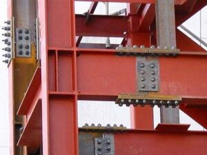
Moment or Rigid Frames
A ‘Moment’, or ‘Rigid’ frame acts in a completely different manner, as there is no bracing to distribute the lateral forces, the frame, and the connections are designed to be either ‘rigid’ or ‘semi-rigid’, thus resisting the rotational moments.
As a result, the columns tend to be heavier than their ‘braced-frame’ counterparts, with thicker flanges, while the end-plates, or splices, likewise, tend to be thicker to resist the bending moments. The horizontal beams however, will be smaller due to the reduced deflection.

As moment-connections are designed to transmit the end-moment from a beam to a vertical column together with the vertical shear, there are essential requirements for such connections, and they include: Adequate Moment Resistance, Rotational Stiffness, and Rotation Capacity.
Moment Resistance
A moment connection may be either Full-Strength or Partial-Strength. A full-strength connection is where the moment capacity is equal to, or larger than, the capacity of the connected member, while a partial-strength connection is less than that of the connected member.
Rotational Stiffness
The stiffness of the connection is termed as either Rigid, or Semi-Rigid. A rigid connection would be stiff enough to resist the bending moments at the beam to column joint by maintaining the angular relationship between one and the other. A semi-rigid connection on the other hand, would allow some rotation, but not enough for it to be classified as ‘Pin-Ended’
Rotation Capacity
The rotation capacity of the connection is determined by the deformation of the thinnest component under load, which may be either, the column flange or the connecting end-plate.
Adjustment of these properties will determine whether the connections will be Rigid or Semi-Rigid.
There are 3 possible cases as shown at the illustration, these include:

Fig 1 - Thick flange / Thick end plate | No Rotation Capacity
Fig 2 - Thick flange / Thin end plate | Rotation capacity determined by the end plate
Fig 3 - Thin flange / Thick end plate | Rotation capacity determined by the column flange
Tension, Compression and Shear Elements

The assumption is usually made with moment connections that the flanges of the beam transmit the rotational moment, the top flange is therefore in tension, with the bottom flange being in compression, the shear component is resisted by the beam web. Any axial force (compression) in the beam is assumed to be transmitted by the flanges and web in proportion to their respective cross-sectional areas, or alternatively by the flanges only.
Consequently, a moment connection is usually identified by the fact that the beam is connected to the column by means of the flanges, as opposed to a Pin-Ended, or ‘Flexible’ connection which connected by means of the web.
Standard Connections
Unfortunately for the draftsman, there is no such thing as a ‘standard’ moment connection, each should be purpose-designed to suit its particular requirements taking into account the required distribution of forces, but on the plus-side, there are a number of guidelines and ‘rules-of-thumb’ that can be applied to assist in ‘economical’ application of the design.
However, we have included some Typical Connections which the detailer can use as guidelines for particular arrangements, they include:
- Site-Bolted End-Cleats
- Site-Bolted End-Plates
- Site-Bolted Flange-Plates
- Site-Bolted Moment-Trees
- Typical Site-Welded connections
Guidelines
- Wherever possible, avoid the use of site-welded connections, the level of accuracy necessary, and the high quality that’s essential for such connections makes them difficult and time-consuming. Often, temporary platforms are necessary in order to gain all-round access to the joint, and in areas of inclement weather conditions it may be necessary to ‘shield’ the area by means of a plastic ‘curtain’.
- If possible, select columns and beams to do the job without the need for additional stiffeners or ‘doubler-plates’. Often a heavier column will prove to be more cost-effective than a ‘stiffened’ lighter section. Discuss issues such as this with the fabricator and refer to the responsible engineer.
- Use Fillet-Welds wherever possible avoiding prepared welds, especially on lighter joints. On heavier joints with thicker plates (over 17 mm) a prepared weld will probably be unavoidable. Again, refer to the responsible engineer.
- Regard 8 mm Fillet-Welds as the largest single-pass, 6 mm being preferable
- On large Fillet-Welds, regard 12 mm as the maximum multi-pass weld due to plate distortion, for welds over 12 mm, consider the use of Partial-Penetration welds (Refer to Welding)
- Resist the use of columns less than 200 mm otherwise the connections can be very difficult, and sometimes impossible. Columns of 250 mm and over should ideally be regarded as minimum.
- When using oversize holes to aid with erection, slip-resistant (Friction-Grip) bolts should be used to make the connection. Ideally, where slip-resistant bolts are required, the beam or splice-plate should be clearly marked indicating that such bolts are to be used, with the bolts ‘bagged’ and attached to the beam.
- The draftsman should always endeavor involve the fabricator and site-erector at an early stage of detailing, and with the input of the responsible engineer, try to develop connections best suited to the fabricators preferences and abilities.
- As a general rule, moment-connections apply exclusively to beam-to-column connections and will be located at the peripheral columns on the external faces of the structure. Like all rules of course, there will be exceptions, but they are few.
Dimensioning Guidelines
Moment connections must be designed and specified by the responsible engineer, unlike Flexible Connections which can be quantified and standardized, moment connections must be considered as part of the structure as a whole. As such, they are not considered in isolations. These Dimensioning Guidelines and the following Rules-of-Thumb are intended to provide the detailer with some insight into some commonly applied rules.
- Edge distances should not be less than 2 x the bolt diameter.
- Bolt hole spacing should not be less than 3 x the bolt diameter in both horizontal and vertical planes.
- When connecting a beam to a column:
- The top bolts resist the moment
- The top bolts should be placed as close to the top flange as practical allowing sufficient clearance for tightening.
- For extended end-plates, the same principle applies.
- The middle bolts, or those in the shear cleats or plates generally are there to resist the shear component - the number should be determined by the responsible engineer
Rules-of-Thumb
There are a number of rules-of-thumb that may be applied to moment connections, though not hard-and-fast design rules, they should provide some insight for the draftsman by knowing what to look for and perhaps gain a better understanding of how these connection types work.
- End-Plate thicknesses should not be less than the bolt-diameter
- On ‘Flange-Plate’ connections, the plate thickness should be equal, or as close as possible, to the beam flange thickness + 10 mm. (See Flange-Plate Connections)
- Bolt-diameters should be M20 for beams up to 400 mm in depth, and M24 for larger beams
- Edge-distances between the edge of the plate and the center of the bolt-holes should not be less than 2 x the bolt-diameter.