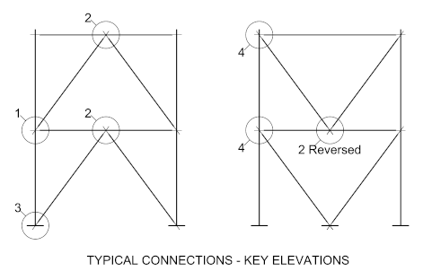
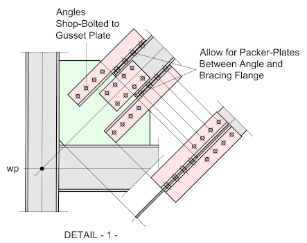
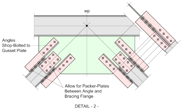
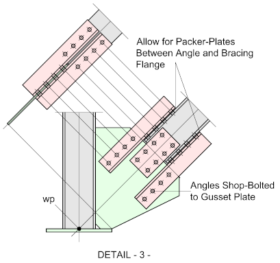
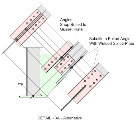
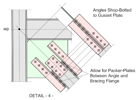
 The following typical connections apply to –I- or –H- profile bracing which may be subject to tension or compression. The flange angles are bolted to the gusset plate and site-bolted to bracing member on erection. This all-bolted option allows for some fabrication alignment (but not much) as the bolt clearance holes will allow for some minor adjustment on site. The difficulty with this option is that it takes up a lot of space – the gusset-plates will always be large, so care must be taken with the design that the plates do not buckle under load – this must always be confirmed by the responsible engineer.
An example of this can be seen in DETAIL -3- where the gusset-plate looks clumsy and ungainly. This of course will depend on the relative sizes on the column and base-plate together with the angle of the bracing. One option that could be considered in such instances, is to substitute the lower angle with a welded flange-plate (DETAIL 3A) - this will save a lot of space, but will need to be analyzed and confirmed with the responsible engineer.
The bracing members are set out to a common Work Point located at the intersection of the centre lines of the beams, columns and bracing members. Other options for locating the Work Points can be found at Vertical Bracing - Setting Out
If the bracing is to work in compression, Slip-Resistant bolts will most likely be required.
The usual rules that apply to the strike-planes will be found not to apply here as the values for spX and spY (See Vertical Bracing - Setting Out) will be determined by the inclusion of the flange plates. In some circumstances the length of the gusset-plate may become excessive and could create a bending moment in the plate, especially if it’s likely to work in compression. This will need to be addressed by the responsible engineer.
In each case the gusset-plates are indicated connecting to the column flange - For further information on connecting to the column web go to Vertical Bracing - Setting-Out
