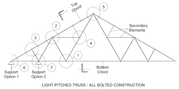
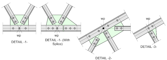
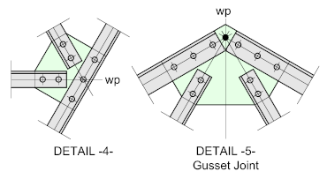
In this example, we show an all-bolted pitched truss (or Fink Truss)

For all-bolted trusses formed using angles, the work points may be established from the centroids or centers of the members. Technically, he correct way is to use the centroids but as the holes are commonly set out on the center-line of the lacing members, many detailers prefer to use these center-lines as the setting-out points. It will inevitably result in some eccentricity at the joints, but these are usually relatively minor and should be able to be accommodated.
As usual, just check this out with the responsible engineer.


For all-bolted trusses formed using angles, the work points may be established from the centroids or centers of the members. Technically, the correct way is to use the centroids but as the holes are commonly set out on the center-line of the lacing members, many detailers prefer to use these center-lines as the setting-out points. It will inevitably result in some eccentricity at the joints, but these are usually relatively minor and should be able to be accommodated.
As usual, just check this out with the responsible engineer.
End Support Options
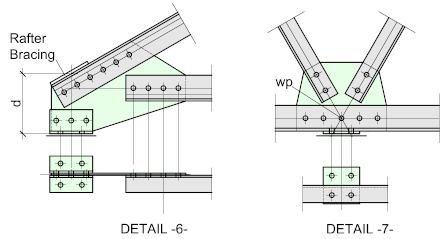
DETAIL -6- illustrates angles bolted to the gusset-plate, which then fasten to the support.
In order to prevent a large bending moment being applied to the shoe, it would be either necessary to stiffen the shoe, or or re-distribute the loads to the end strut of the rafter bracing.
(Rafter bracing will be covered later in this series)
DETAIL -7- shows a typical connection for a cantilevered truss. A simple base-plate is welded to the underside of the bottom chord which should align with a node.

