REVISIONS TO PAGE
- References to Fig's 1 - 4 corrected
Moment connections may be either shop-welded / site-bolted, or shop-welded / site-welded. By far the most common is the shop-welded / site-bolted, examples of which are illustrated below and include:
Bolted End Cleat Moment Connections
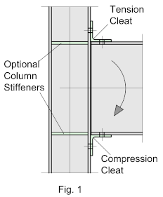
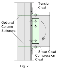
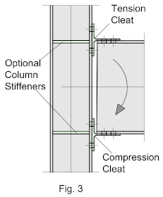
End-Cleats are shop-bolted or welded to the top and bottom flanges of the incoming beam. They are the simplest and most cost-effective moment connection type with regards to both fabrication and erection. But due to their inherent flexibility, they are usually limited to single storey or low-rise structures in areas of low seismic activity. The connections can be made with standard hot-rolled angle sections, Tee-sections or heavier fabricated sections, which will to some extent improve the strength of the connection.
Fig. 1 Illustrates a Typical connection using top and bottom cleats
Fig. 2 shows the same connection with an additional web cleat to improve the shear resistance
Fig. 3 Illustrates the same moment connection using standard Tees
There are some questions as to whether Cleat connections can be classified as ‘Moment-Resisting’ at all, but the disposition of the elements of the connections suggest they should be, albeit in limited applications.
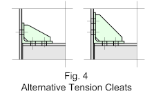
To increase the moment resistance, The top cleats (Tension Cleats) may also be stiffened (Fig. 4) This can be done by using a long leg unequal angle with a central stiffener welded into the web or a larger cleat. Though Column web stiffeners are shown as an option, they are rarely required as the rotation capacity of the cleat will, in most cases, exceed that of the column flange.
Note!
For the spacing of holes and general dimensioning guidelines see Guidelines > Dimensioning Guidelines
End Plate Moment Connections
Bolted End-Plates are shop-welded to the beam-end and site bolted to the column. The end-pates may be either ‘Flush’ or ‘Extended’, A ‘flush’ end-plate is detailed so that the end-plate does not appreciably extend beyond the beam flanges and all bolts are located between the beam flanges
An ‘extended’ end-plate is detailed so that the plate extends beyond the tension (top) flange and may be either stiffened or un-stiffened. The plates may also extend beyond the compression (bottom) flange, and likewise, may be either stiffened or un-stiffened.
End-Plate connections may be either ‘rigid’ or ‘semi-rigid’ depending on how it’s designed. The rigidity of the connection is dependent on its Rotational Capacity
End-plate moment frames have been used for structures of up to 30 stories in areas of low seismicity, and up to 10 stories in areas of moderate to high seismicity.
Typical examples are shown below:
Fig. 5 - Shows a typical Flush end-plate connection
Fig. 6 - Shows a typical top extended end-plate
Fig. 7 - shows a typical moment end plate extended top and bottom
Fig. 8 - shows a typical moment end plate extended top and bottom with a top stiffener
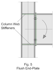
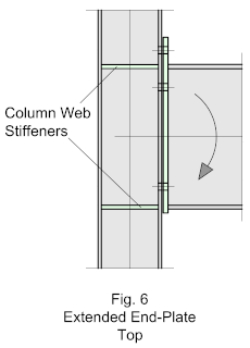
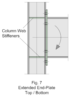
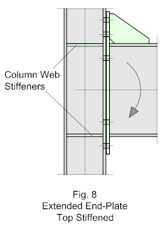
When connecting to the column flange it may be necessary strengthen the column by adding Stiffener-Plates between the flanges, stiffeners are time consuming and expensive to fit, so they should only be added where necessary. Stiffening must be the responsibility of the engineer.
When connecting to the column web, being the weak axis, horizontal full-depth stiffeners will usually need to be added adjacent to the incoming beam and in-line with the beam flanges.
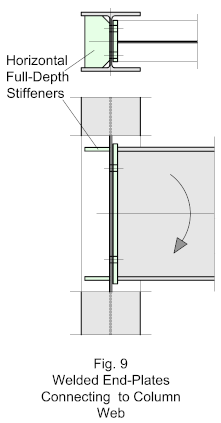
Flange Plate Moment Connections
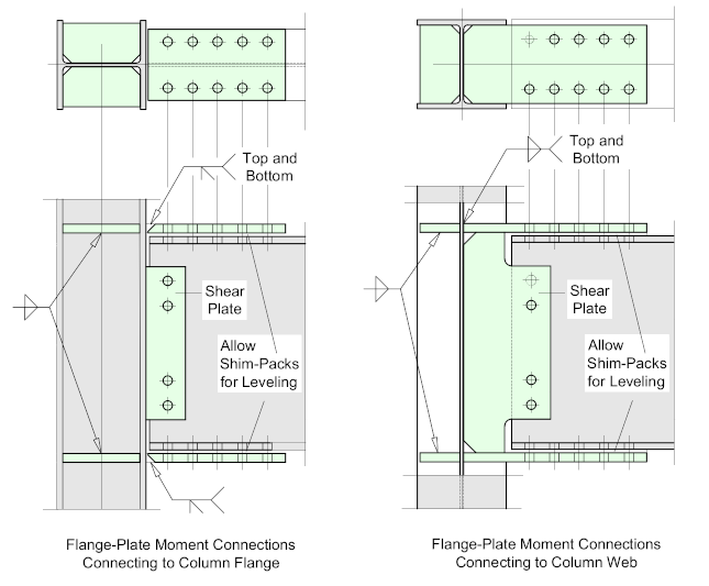
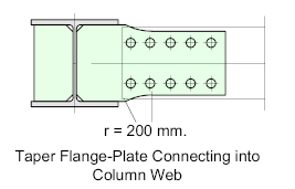
Flange-plate, or moment-plate connections are generally considered to be ‘fully-restrained’ or ‘rigid’. The flange-plate is shop-welded to the column while the beam is fitted between the plates and site-bolted through the flanges and flange-plates. Shims are provided between the mating faces to facilitate erection and alignment. Alternatively, the flange-plates may be shop-welded alternately to the column and beam and site-bolted during erection. When connecting to the column web, the flange-plate should be welded to the inside flanges of the column. If the column is larger than the incoming beam it may be necessary to ‘taper’ the flange-plate to ensure proper fitment.
Column Stiffeners are usually required.
A shear-plate is shop-welded to the column and site bolted to the web of the beam.
To facilitate erection, oversize holes may be used in the moment-plates, while horizontal slotted-holes may be used in the web shear-plates.
Fillet-welds may be used for small beams with a flange thickness of less than 17 mm, while for beams with thicker flanges, a prepared weld will be required. However, as the weld is fundamental to the strength of the connection it should be properly designed and clearly specified.
Note!
For further insight into detailing flange plate connections see the information provided under Guidelines together with some useful Rules-of-Thumb
Column Tree Moment Connections
In moment-tree connections, the ‘stub’ is shop-welded to the column and ‘spliced’ to accommodate the connecting beam. This construction method reduces the demands on the connection by moving the ‘hinge-point of the connection away from the column to the splice, significantly reducing the stress concentrations at the beam / flange weld.
The bolted-splice acts as a ductile ‘link’ to limit the bending moment that can be developed in the frame and depending on the bending strength and rotational stiffness of the splice, the column tree may behave as a ‘rigid’ or ‘semi-rigid’ moment resisting system.
Consequently, connections of this type are frequently used in seismically active areas, where the connection could be subjected to repeated cyclic loading during an earthquake.
Such frames can sometimes be difficult to erect because the connection is located away from the column, consequently, temporary erection platforms may need to be provided.
Column Stiffeners are usually required
Some Useful Rules-of-Thumb for Moment-Trees
- The thickness of the plate should be at least as thick as the incoming beam flange thickness, rising to Flange Thickness + 10 mm
- For beams, less than 400 mm deep, use M20 bolts. For larger beams use M24
- Welding should be Fillet-Welds, provided full-penetration can be achieved, (Refer to – Welding)
- The Stub length will usually fall between the range of 600 – 1000 mm.
Connecting to the Column Flange
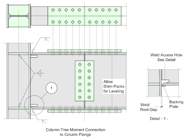
Weld Access Hole
The Weld Access or Rat Hole in the web of the beam allows the welder to weld the full width of the beam flange to the column, which would otherwise be blocked by the web of the beam. In moment connections, the flange joint is important because it resists the bending moment of the beam.
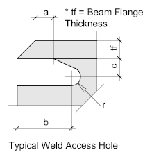
| Weld Access Holes | |
| tf | Beam Flange Thickness |
| a | tf or 10 mm. Whichever the Larger |
| b | 3 x tf |
| c | 20 mm |
This example is fairly typical and will be found to work for most applications, BUT – as with all critical connections the detail must be approved by the responsible engineer.
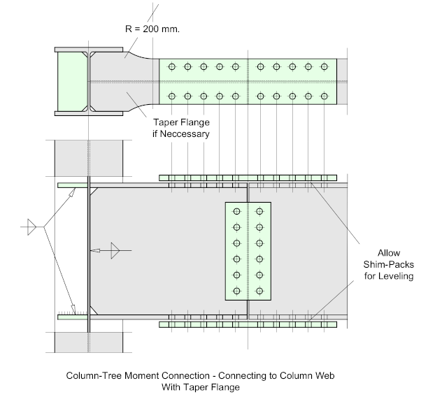
Connecting to the Column Web
When connecting to the column web, the flange-plate should be welded to the inside flanges of the column. If the column is larger than the incoming beam it may be necessary to ‘taper’ the flange-plate to ensure proper fitment.
Web Stiffeners should be welded inside the column flanges adjacent to the incoming stub flanges
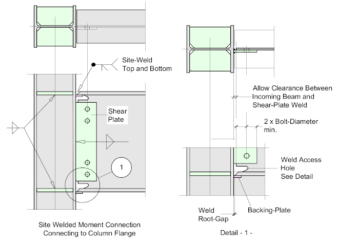
Site Welded Moment Connections
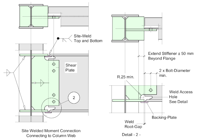
Site-welded moment connections, where the beam is welded directly to the column was common practice until the mid-1990’s when the Northridge earthquake in California USA exposed a few deficiencies in the practice, and consequently their use has diminished in favor of the shop-welded / site-bolted system.
Though such connections are fairly straightforward to design and economical to detail and fabricate, the fact that the critical weld is made under, what are essentially, uncontrolled conditions will always create doubt as to its quality. There are many factors that can influence the quality of a site-weld, not least among them are the climatic conditions and access to the joint itself, especially if it’s to be made at high elevated positions.
Note that the weld preparations are configured for down-hand welding.
Column Stiffeners are usually required
Connecting to the Column Flange
Connecting to the Column Web
