Gusset Plate Geometry
Gusset-plates are the most common means of connecting bracing, they may act either in tension or compression depending on how the bracing is configured.
They should be as compact as possible to minimize the risk of out-of-plane buckling when in compression.
When setting out the bracing, it should be borne in mind that as it approaches the upper and lower limits of the bracing angle, the gusset plate will always increase in size.
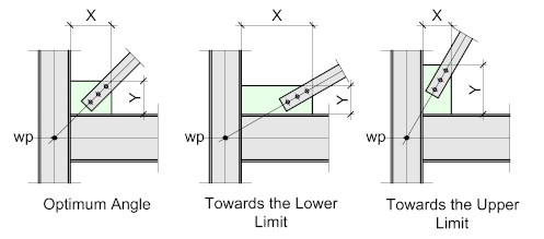
A well-proportioned configuration is when the relative sizes of the beam and column do not exceed 1.5 as indicated above – but when this value increases and the bracing is set out towards the upper and lower limits the greater will be the impact on the geometry of the plate.
If the gusset plate is acting in tension, then a large gusset plate can probably be tolerated, but if it's acting in compression then the risk of out of plane buckling is increased - this could result in a gusset plate failure. To negate these effects there are a number of possible options:
- Increase the thickness of the plate.
The thicker plate will offer more resistance to out-of-plane buckling. - Stiffen the gusset plate by welding additional stiffeners.
Though this is technically an option, it can be a lot of work and be costly and time-consuming.
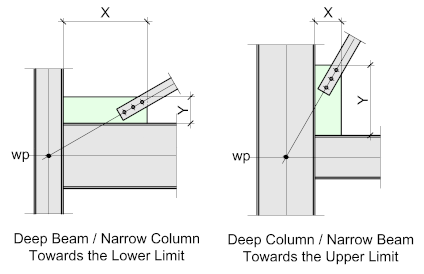
- Reduce the gusset plate size by fixing it to either the beam or column only.
This should only be considered for lightly loaded connections acting in tension. To make this connection type work, the bracing members must be perfectly in line with the Gusset-Plate, any misalignment will expose the Gusset-Plate to bending and possible fatigue.
This arrangement should not be used if the bracing members are likely to be subjected to compression. The general rule is that compression bracing must fix at two edges (to the beam and column) - Relocate the Work Points.
This may seem to fly in the face of everything that's been said up to now, but it is a valid option and will work for most applications where the bracing is connected to the beam or column flange. If the resulting eccentricity (e) is small, it can be reasonably assumed that the thickness of the flange will resist the resulting moment.
This is a common solution and will ensure a compact gusset-plate.

Gusset Plate Types
Gusset-plates may be either welded or bolted.
The following examples assume the work-points are placed at the intersections of the center-lines of the component members with the bracing set at the optimum angle.
They are all set-out assuming the connection is made to the column flange – they can all be adapted to connect to the column web provided care is taken to assure the connections will fit between the inside flanges.
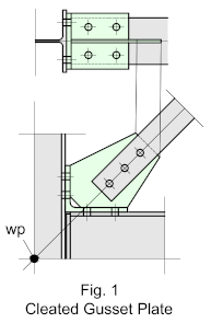

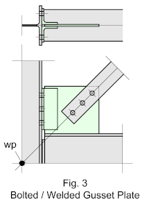
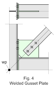
Fig 1 - illustrates the cleated gusset-plate, which is usually fabricated from a standard hot-rolled angle section, but if the requirements fall outside the standard range, may be fabricated. The cleat, with the gusset-plate welded inside the legs, is shop-bolted to the flange of the beam and site-bolted to either the column flange or web.
This arrangement works best when the beam and column are proportioned to a ratio of not greater than 1.5 : 1 and the bracing angle is close to optimum. It does not lend itself to extended gusset plates or when the angles approach the upper and lower limits
This gusset-plate arrangement will work with any end-plate, cleat, or seated connection.
Fig 2 - Illustrates a bolted gusset plate, where the plate is ‘sandwiched’ between two angle cleats, the cleats are shop-bolted to the flange of the beam and site bolted to either the column flange or web.
This gusset-plate arrangement will work with any end-plate, or cleat connection
The same limits apply as for the cleated gusset-plate.
If the plate is acting in compression, it should be checked for out of plane buckling.
Fig. 3 - Illustrates a bolted / welded gusset plate, where the plate is shop-welded to the flange of the beam, and site-bolted to the column by means of the cleats
This gusset-plate arrangement will work with any end-plate, or cleat connection.
Note that the strike plane, as with Fig. 2 above will be located at the toe of the site-bolted angle cleat.
Fig. 4 - Illustrates a welded gusset-plate, which is shop-welded to the flange of the beam and the inside face of the extended end-plate. The end-plate is site-bolted to the column.
This gusset-plate arrangement is designed to work with extended end-plates.
This arrangement will change the fixity of the connection meaning that it may not be strictly 'flexible' however, this is a very common option as it allows greater flexibility with regards to the angle of the bracing.
Gusset Plate Shapes and Bracing Connections
Gusset-plates may be welded or bolted and may be either square-cut or shaped.
The Square Cut gusset-plate will always be the most economical in terms of material usage
The Shaped gusset-plate, where the corner is cut at right-angle to the bracing member is probably the most common, even though there is an extra cut and more material. The width of the corner cut is not specific – it may be equal to the bracing member width, or can extend up to 100 mm.
The Profiled cut is often used when the plate length becomes excessive – It does have additional cuts and additional pre-cut material, but when balanced against the additional shop-welding could prove to be more economical.
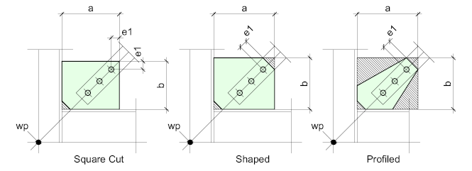
The ‘e2’ dimension is the recommended edge distance, while ‘n’ represents the number of holes spaced according to the recommended spacing. (For more information on this, refer to Edge-Distances and Bolt-Hole Spacing.
The ‘Distance’ is as calculated earlier.
If the beam and column are of the same depth and the bracing set out to an angle of 45° - the sop’s offset will appear at the corner of the plate – however, in most cases this will not be the case, so the intersection of the bracing line (sop) will most likely be offset to the plate – this will vary according to the relative member sizes and the bracing angle.
Dimensions A and B are the overall sizes (Pre-cut) of the plates. Though not essential, it’s always a good idea to round up the actual size of the plate, at least in one direction, to a round figure
