Here, we’ll be looking at the setting-out procedure for Concentric vertical bracing using gusset-plates, the general principles will apply to all bracing configurations irrespective of member sizes. Concentric bracing implies that the Work-Points are derived from the center-line intersections of the beam, column, and bracing member. The center-lines represent the neutral axes of the members, thus ensuring an efficient load distribution throughout the structure.
It is understood that if angles are used for the bracing members, the center-line is not the true neutral axis, but working with the center-line of the angle simplifies the setting-out and detailing considerably – meaning that the setting-out points and the connecting bolt-holes are symmetrical about the connection.
Like all rules, there are exceptions, which we’ll look at later in this post when we consider Gusset-Plates.
However, when working with lightweight welded structures such as trusses and gantries, it’s important that the true neutral axis be observed. (See Trusses)
Here, we’ll be concentrating on bracing using gusset plates.
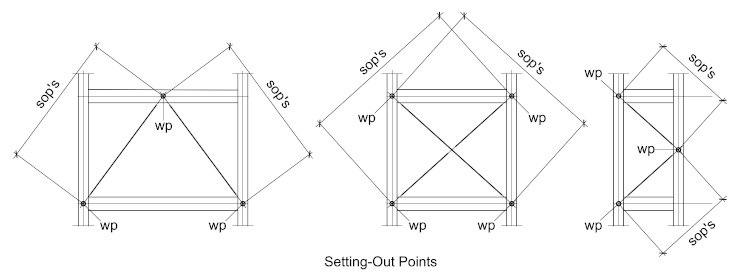
Once the work-points are established the distance between them along the bracing line are referred to as the Setting-Out-Points – from here it’s a simple matter to determine the bracing length.
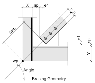
The X and Y axes measure the center-lines of the beam and column to the outside face of the flange, while the value for ‘sp’ is the distance between the corner of the bracing member and the strike-plane of either the beam and column.
Whether it’s the column or beam will depend on the relative sizes of the two and the bracing angle – the lowest value should be assumed.
The value for ‘e1’ is also a function of the bracing angle size and the angle. Here, the advantage of using the center-line of the bracing member is apparent.
The result will give the distance (Dist.) from which the actual length of the bracing can be established by subtracting the top and bottom distances from the setting-out-points (sop’s)
For those working with CAD – the software will do most of the heavy lifting with the only decision made by the detailer being the distance to the strike-plane.
This we’ll look at now
The Optimum Angle
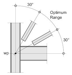
Ideally, bracing should be set out at an angle of between 30° and 60° when measured from the horizontal plane with the optimum being 45° - this will ensure the most efficient distribution of the lateral loads through the structure into the ground.
Additionally, it will ensure the most compact gusset-plate, simplifying the design by reducing the risk of out-of-plane buckling
Strike Planes
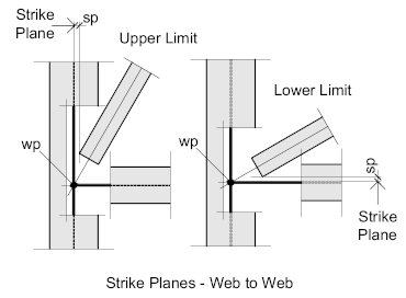
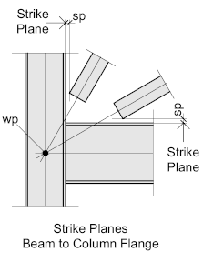
The strike plane is represented by the closest point of contact between the bracing member and the structural members, which may be either the beam or column.
This distance (sp) should be somewhere in region of between 10 and 20 mm. taking into account any connection components such as the end-plate or cleats and any protruding bolts.
Depending on how the beam and column are orientated, the strike plane may be either the column flange or web.
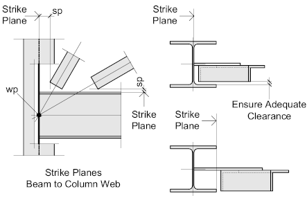
When connecting to the column web, the detailer should ensure that there is sufficient clearance between the bracing member and the inside face of the flange – if not – the shear plane must be assumed to be the toes of the column section.
Less common is when the beam to column connection is orientated so that the webs of both members form the strike planes - in such cases, again, ensure there is adequate clearance between the inside faces of the flanges on both members.
Next is to look at the connection itself:
