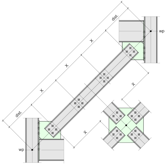
 The following typical connections are for channel section bracing which may be either single or doubled back-to-back, being the more common. This type of bracing usually requires a double row of bolts equally spaced about the centre-line of the bracing member.
The general rules-of-thumb for the spacing of the battens applying to Angle bracing may be applied to channels.
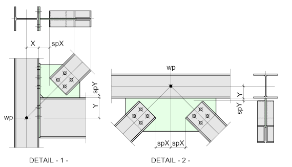
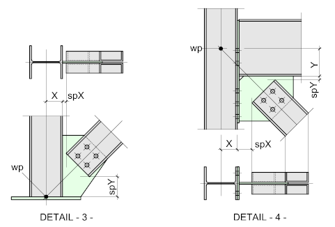
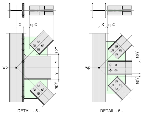
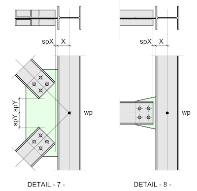
The channels are set out to a common Work Point located at the intersection of the centre lines of the beams, columns and bracing members. Other options for locating the Work Points can be found at Vertical Bracing - Setting Out
The Strike-Planes are represented by spX (Vertical) and spY (Horizontal). The relative sizes of the column and beam together with the angle of the brace will determine which of the two will be the lesser. The lesser value should ideally be between 10 and 20 mm. This will ensure the joint is compact while allowing for normal fabrication and erection tolerances.
For more information on Strike-Planes refer to Vertical Bracing - Setting Out
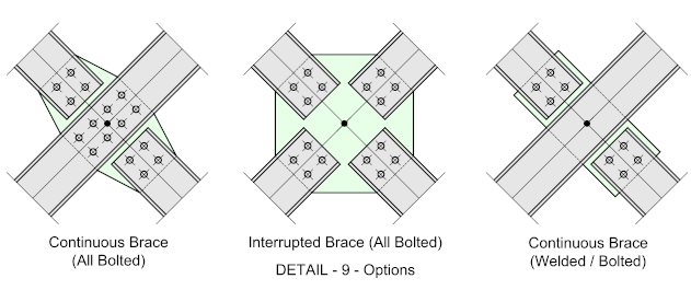
Though the gusset plate illustrated is the welded type, which is used with the end-plate connection – the all-bolted cleats or plates may be used together with the bolted / welded type. For more information on these and the various gusset plate shape options go to Bracing Gusset Plate Connections
In each case the gusset-plates are indicated connecting to the column flange - For further information on connecting to the column web go to Vertical Bracing - Setting-Out
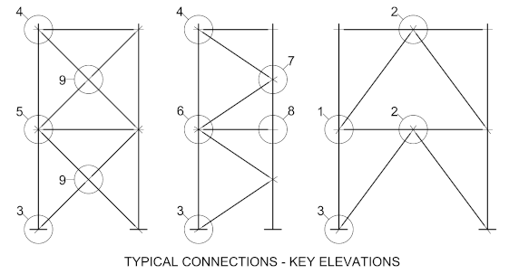
Battens
Any bracing member comprising of double (back-to-back) members should be battened, battens ensure the bracing members act as a single unit. The thickness on the batten plate should be the same as the gusset-plate, while the overall size should match that of the bracing section, i.e. a 180 x 70 channel connecting to a 10 thick Gusset plate would require a 180 x 180 batten plate, based on the assumption that there would be 4-holes per plate. In some instances a 2-bolt plate would be acceptable, in which case, the batten plate may be reduced to 180 x 70.
Battens are bolted between the bracing members.
Spacing of the battens is at the discretion of the responsible engineer, but as a Rule-of-Thumb, 6 / 8 x the channel depth will often prove adequate i.e. for the 180 x 70 channel, a reasonable spacing would be between 1080 and 1440.
The spacing is always measured from the last hole on the gusset plate to the centre of the batten – the gusset-plates forming the first and last battens. If there is a centre gusset plate, the same principle applies – see illustration below
