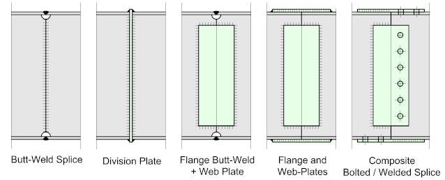
Welded beam splices come in many forms, but generally, as mentioned earlier, unless there are compelling reasons otherwise, they are usually considered to be ‘shop’ welded. The welded joint usually has to develop the full strength of the beam or girder which means that the welds (of at least the flanges) must be prepared, full penetration Vee-Butt welds.
Such welds would normally be tested according to their criticality and the design requirements.

The examples illustrate typical welded splices found on standard hot-rolled steel sections, they will all work and are commonly encountered in steel structures, with the exception of the composite bolted / welded connection.
It should be clear from the following illustrations that each of these types has an application, the Butt-Welded splices, with or without the division plate are designed for straightforward moment resistance, while those with web plates are for higher moment resistance and shear.
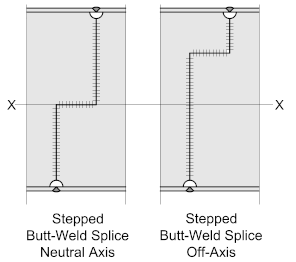
Large beams or girders may require a ‘stepped’ butt weld for the web (see illustration), increasing the amount of weld material in keeping with the principle of the web having to share some of the moment resistance.
There is a school-of-Thought that suggests when stepping the weld its good practice to place the step as close as practical to the beam flange and not at the center of the web, which being the neutral axis, will not be effective.
Check this with the responsible engineer

Butt-Welded Flange Joint / Bolted Web Plates
When Splicing Large Plate-Girders an option is to butt-weld the flange plates while bolting the web-plates. In connections such as this, the web-plates must be bolted first, followed by the flange Butt-Weld, and finishing by welding the web to the flange at the joint.
For such connections, it’s common practice to provide ‘weld access holes’ at the flange joint to facilitate the deposition of the weld material and any back-gouging that may be necessary, and to provide access for inspection. They will also provide access for backing plates, should they be required.
It should be noted that weld access holes (or cope holes), should only be used for statically loaded girders. In dynamically loaded girders, such as Crane Gantry Girders, the discontinuity at the cope could act as a stress raiser potentially leading to fatigue failure.
Check this with the responsible engineer!

Note 1. Length should be greater than 1.5 the flange thickness but not less than 38 mm
Note 2. Depth should be greater than the flange thickness or 20 mm, but not greater than 50 mm.
Note 3. The web-to-flange weld should be held back a distance of at least the weld size from the edge of the access hole
Note 4. The arc of the hole (r) should not be less than 10 mm
Splicing Beams of Different Sections
Splicing beams of different sections is not a common occurrence, the operation tends to be expensive and time-consuming, not to mention ‘tricky’ as the tolerances involved are tight. So, unless there are compelling reasons it should be avoided wherever possible.
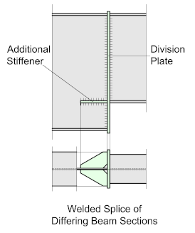
Splicing a beam of differing depths will usually require the addition of a ‘division-plate’ to which the flanges and web of the two halves are welded. A division-plate stiffener is often placed adjacent to the flange of the smaller section.
Such details should always be confirmed by the responsible engineer.

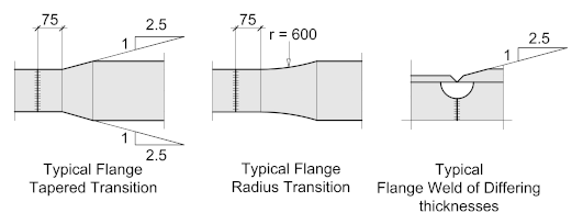
Splicing a beam of different flange widths will require that the flange of the larger section be ‘tapered’ at a ratio of 2.5 to 1 to avoid the stress-raisers that would be present if the flange was ‘stepped’ at 90°. After the taper, the flange should extend approximately 75 mm.
The transition may be either ‘tapered’ or ‘radial’ at approximately 600 mm radius.
Likewise, when splicing flanges of different thicknesses, the thicker flange should be tapered and not ‘stepped’ at a ratio of 2.5 to 1, leading to the weld preparation.


IS THERE ANY MINIMUM DISTANCE FROM THE BUTT WELD OF WEB TO THE HOLE EDGE ?? IN THE LARGE PLATE GIRDER SPLICE ??
drsuresh.srinivasan@GMAIL.COM
Ideally, it should not be less than 2 x the bolt diameter.