Introduction to Lateral Restraints
In lightly loaded short-span Crane-Girders the top-flange of the girder may be stiffened by fixing an inverted channel horizontally to give additional support and to resist lateral loading from the crane wheels.
However, the channel itself only offers limited resistance against anything but the lightest lateral load conditions, consequently, in most cases it will be necessary to restrain the top-flange of the crane-girder back to the building structure by means of some form of Tie-Back or Surge-Girder.
The means of providing this restrarint will vary according to the imposed loads generated by the duty cycle of the crane.
Here. we'll look at the various means of restraint from the simple Tie Back for light duty cranes, to Surge Girders for medium to heavy duty applications and horizontal lattice girders for heavy to extra-heavy applications.
Light-Duty Applications
A typical light-duty application would involve the use of a standard hot-rolled beam section mounted on the corbel of a portal-frame column.
As the connection between the crane-beam and the column is supposed to be nominally-pinned only a single bolt is used for flexibility. The bolts in the bottom-flange should be sufficient to allow continuity of the longitudinal forces.
These are typically ‘hand-tight’ which may be tack-welded after installation to ensure the nut does not work loose.
For lateral adjustment slotted holes are provided in the support bracket, and packing should be allowed between the tie-back and column connection, the thickness of which should correspond with the lateral adjustment.
Shims may be provided under the bottom-flange for vertical adjustment.
Generally, the crane-beam would be fastened back to the column by means of some form of Tie-Back, typical example of which are illustrated in Figs 1 – 4.
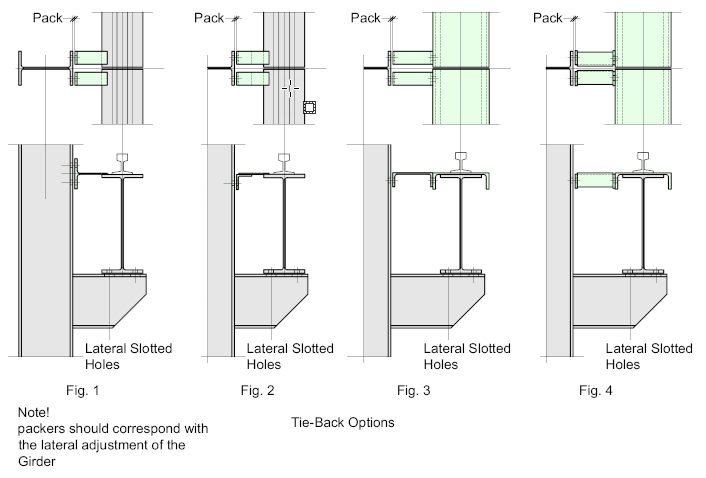
Fig 1 – Indicates a Tee-Section which is usually shop-welded to the top-flange of the crane-beam and site-bolted to the column
Fig 2 – Shows a similar arrangement with standard ‘Flats’ welded to the top-flange with a connecting angle welded to the flat and site bolted to the column flange.
Fig 3 – indicates an inverted channel section which is shop-bolted to the channel flange and shop-bolted to the building column.
Fig 4 – indicates a similar arrangement with the channel substituted by angles. This configuration is used when a standard channel will not work.
Medium / Heavy-Duty Applications
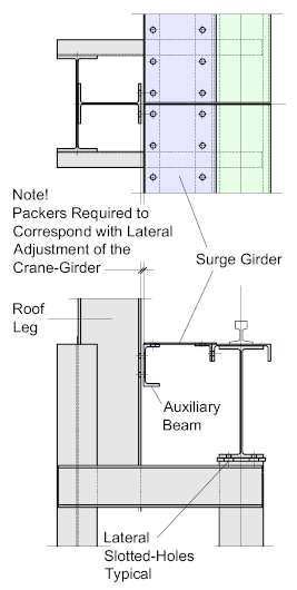
For heavier loads, especially where wide-spans are involved, lateral support should be provided by some form of Surge-Girder. A typical example would be as illustrated, which shows an auxiliary beam spanning between the columns to which a surge-plate is bolted spanning the full length of the crane-beam.
For this application it’s assumed that a twin-column is used, with the crane-beam or girder connected to the crane-leg, while being restrained against the roof-leg.
In most cases, where standard hot-rolled beam sections are used the flanges of the crane-beam will be stiffened with an inverted channel stiffener. Apart from providing additional rigidity, it forms a very convenient means of attaching the surge-girder plate.
Provided the crane-beam or girder flange is of sufficient width, it’s common practice to bolt the surge-girder plate to the top-flange.
But for narrow flange beams the plate can interfere with the crane-rail-clips, in which case a standard angle mat be bolted (or welded) to the inverted stiffening channel
Notes on Surge-Plates
The primary purpose of the surge-plate is to provide the necessary support to the top flange of the crane-girder against lateral torsional buckling generated by the crane wheels. This force will vary according to the size and class of the crane.
The top flange of the girder, the surge-plate, and the auxiliary beam, or girder, act together to form a horizontal plate-girder, and the method of fastening these components together should be designed to transfer the longitudinal shear generated by the lateral bending. The reason for considering the top flange only is that the bottom flange is considered ineffective in contributing to the lateral bending resistance.
The means of fastening these components together may be by welding, bolting, or riveting, but as few workshops today are equipped for riveting, it’s not generally considered as a serious option.
Welding is very efficient, but the welding procedures must be rigid to prevent plate buckling and distortion, which could lead to problems further down the line. Fatigue could also become an issue due to the unequal deflection of the girder and auxiliary beam under repeated vertical loading.
Bolting is probably the most common, but due to the lateral shear forces the bolts may have a tendency to ‘slip’ compromising the stiffness of the girder, for this reason ‘slip-resistant’ bolts should be used for all but the lightest applications.
As the fasteners are necessarily placed close together and run the full length of the girder, it’s obvious that large numbers will be used resulting in costs becoming an issue.
The temptation will always be there to use a lower grade of bolt, but any initial savings could be lost in future rectification and maintenance.
If the girder is to be shop-assembled, then all of the fastening options become available. Welding can be strictly controlled and verified, while the use of ‘Huck-Bolts’ or something similar could be used as a substitute for slip-resistant bolts.
Site-assembly limits the options somewhat. Welding must be carefully considered due to potential lack of control, while ‘Huck-Bolting’ requires a very high level of accuracy during fabrication, even temperature differentials can complicate this process.
Bolting, remains the easiest, if not the costliest option.
Usually, the Surge-Plate is fabricated from raised-pattern floor-plate enabling the girder to double-up as a walkway.
Medium Heavy Duty Horizontal Lattice-Girders
An alternative to the Surge-Plate is the Horizontal Lattice-Girder. It has the advantage of being light-weight, compact and easy to install, however it has the disadvantage of not being as structurally efficient as the plate -girder due mainly to the fact that the concentrated forces at each node-point are resisted by only a few bolts which can tend to work loose. As such, slip-resistant (HSFG) bolts are a necessity, and even those may tend to work loose.
As a consequence, Lattice-Girders require regular inspection and maintenance.
Another disadvantage is that the open nature of the lattice-girder prevents it
from being used as a walkway, and as this configuration requires regular maintenance, this presents somewhat of a problem.
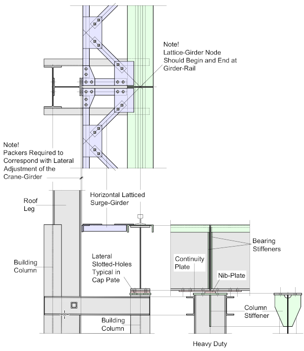
As with the Tie-Backs, the crane beam or girder is fastened to the column-cap which has horizontal slotted holes for lateral adjustment. Packers are provided for the lattice-girder connection to the column roof-leg.
The connection between the column cap-plate and the crane-beam utilizes the continuity-plate for longitudinal continuity, while the girder-end rests on a Nib-Plate, ensuring that the crane-beam or girder is simply-supported.
Heavy / Extra-Heavy-Duty Applications
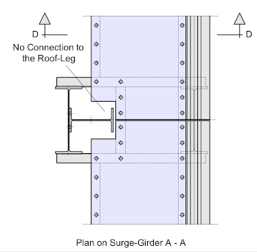
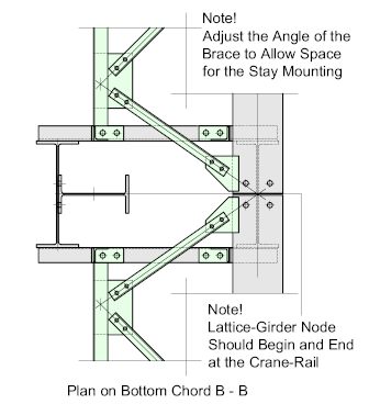
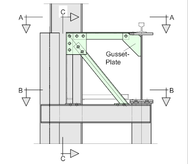
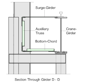
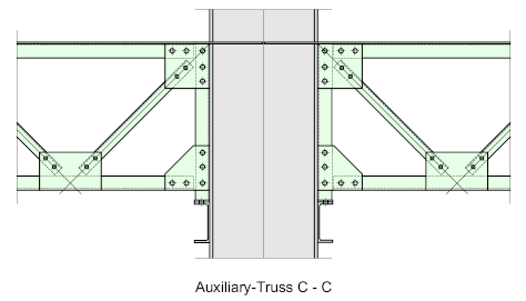
Heavy-Duty application would typically apply to cranes of over 50 T. capacity, which effectively form a box-girder spanning between the building columns. The top chord is formed by the surge-plate which is either site-welded or
bolted to the top-flange. The Bottom chord is formed from a latticed-girder, tying the bottom-flange of the crane-girder to the horizontal auxiliary girder.
The horizontal latticed-girder spans between the columns and is connected to the top batten of the twin -column. The girder does not connect to the roof-leg.
The connection between the crane-girder and the column cap utilizes the continuity-plate for longitudinal continuity, while the girder ends rest on a ‘Nib-Plate’, ensuring once again that the girder is ‘simply-supported. In this instance, the girder is not bolted through the nib-plate but rather adjacent to it. The bearing-stiffeners and Column stiffeners are as previously noted.
Details to Avoid !!
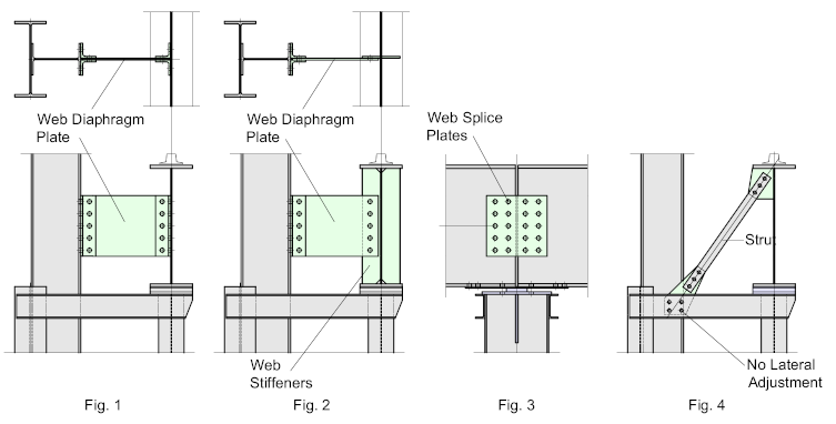
Generally, any Tie-Back or Diaphragm connecting to the crane-girder web should be avoided. Under cyclic, repetitive loading such connections are prone to fatigue and cracks are likely to appear in the diaphragms. Figures 1 and 2 – illustrate such connections.
Splices should also be avoided joining the crane-girder ends together because the ends of the girders are subject to shortening and end-rotation under load. Figure 3 – indicates a web-splice, but the principle applies to any means of joining including: lateral-cleats 0r end-plates which share common bolts, or any form of joint or splice connecting particularly the top flange which must be free to rotate. (Refer back to Continuity-Plates)
Lateral restraint of the crane-girder should only be done by means of the methods previously illustrated. The restraint should be stiff as otherwise differential movement will occur when the two adjoining girders are subject to different loading. For example, when crane lateral loading is present in one girder but not in the other.
In the case of simply-supported girders where lateral adjustment is provided by the slotted-holes in the bottom flange of the girder (or column-cap) the strut, as indicated, will inhibit this adjustment. If the strut is connected to the horizontal member by means of a base-plate with lateral slotted holes, allowing for such movement, it will remain ‘loose’ and will slip under the operational lateral forces reducing the fixity of the girder.
