Fabricated plate-girders are used in long-span applications where commercially available sections are either unavailable or unsuitable. They comprise of two flange plates and a web plate configured into an ‘I’ or ‘H’ profile. They may be either bolted of welded and can be fabricated to almost any size.
Bolted Plate Girders
Bolted Plate Girders are typically fabricated from 2 flange plates and web plated which are bolted or riveted together using hot-rolled steel angles.
They really date back to a time when welding technology was in its infancy and riveting was common. The finished profile has all the advantages of the welded version but the cost of putting it together has proved prohibitive which has rendered them virtually obsolete today in favor of the welded girder.
There are many examples of bolted/riveted girders to be found on bridges built in the late 19th, up to the early 20th century - and the fact they are still standing is testament to their integrity

Welded Plate Girders
Welded plate-girders are now the norm, automatic CNC (Computer Numerically Controlled) welding has streamlined the production of plate-girders, resulting in high quality at a competitive cost. Often plate-girders are ordered to size and length from specialist fabricators, who, having the necessary equipment, are able to produce them efficiently to a high quality
The web and flange plates are usually welded by means of a continuous fillet without the need for end preparation of the web-plates, provided adequate preparation can be achieved (usually up to a 16-mm thick plate. Above this, some form of weld preparation will probably be required
Strengthening a Plate Girder
Intermediate Flange Stiffeners
The flange of a Plate-Girder should never need to be strengthened, if you need to improve the bending capacity of the girder it’s easier to simply select a thicker flange plate.
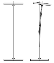
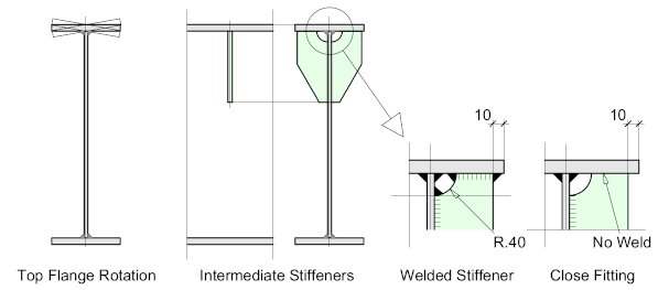
However, there may be instances where the girder has to support substantial point-loads which may cause deformation of the top flange. In such cases, intermediate stiffeners should be placed at the point of loading.
There may also be instances where the top flange will be dynamically loaded such as in the case of a Crane-Girder where the top flange is subjected to repeated cyclic loading which may be compounded if the crane rail is (even slightly) misaligned.
To prevent this, it’s accepted practice to provide intermediate stiffeners at regular intervals along the length of the girder equally spaced between the Intermediate Stiffeners. The stiffeners may be either welded or fitted to the inside flange.
This repeated cyclic loading may lead to cracking of the flange / web weld on the girder, in which case, the ‘snipe’ will need to be engineered. For more information on this see Crane Girders
Web Stiffeners
Welded Plate-Girders however frequently need to be strengthened with web-stiffeners where the web-depth to thickness ratio is higher that would be found on a standard hot-rolled section leading to the potential of web-buckling. There are basically 3 types of web-stiffener:
- Intermediate Transverse Web-Stiffeners
- Longitudinal Web-Stiffeners
- Bearing Stiffeners
Intermediate Transverse Web Stiffeners
Intermediate transverse web stiffeners are situated at intervals along the length of the girder to prevent web-buckling. Intermediate stiffeners are commonly welded to only one side of the web (usually the outside face) but may be welded to both sides (as illustrated) depending on requirements.
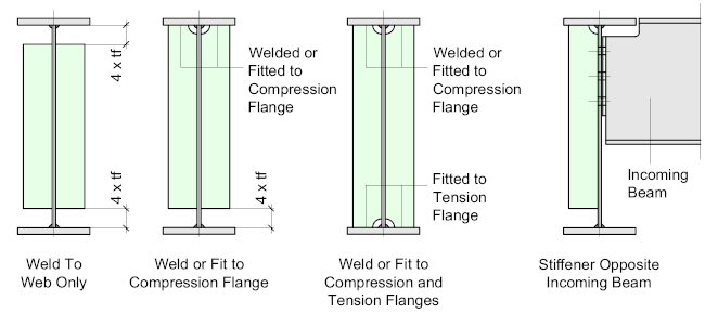
Web stiffeners are also commonly located adjacent to incoming beam connections where there is the possibility of web-buckling due to rotational moments at the connection. The likelihood of this increases as the girder depth increases.
Stiffeners may be either welded to the web only, welded or fitted to the Compression flange, or welded or fitted to both tension and compression flanges. Connection to the flange depends on whether forces need to be transferred from the flange.
Generally, Transverse stiffeners are welded to the top, or compression flange to counter any potential rotation of the flange under load which may result in fatigue problems between the flange and the web weld.
It’s common practice to not weld the stiffener to the tension flange, leaving a gap of approximately 50 mm, or 4 x the flange thickness, provided the stiffener is not required for bearing.
This gap eliminates the need for unnecessary welding and the possibility of a build-up of water or debris which may lead to future corrosion problems, especially if the girder is to located outside and exposed to the elements.
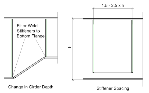
Transverse stiffeners are only welded or fitted to the bottom, or tension flange at points of change in direction of the flange plate.
Fitted or Close-Fit Stiffeners
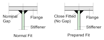
Where a stiffener is welded to a flange, normal fabrication tolerances will apply leaving a nominal gap between the stiffener and flange, in such cases the forces will be transferred through the welds.
If the stiffener is ‘fitted’, the stiffener end will have to be prepared to ensure a close fit between the surfaces thus transferring the forces directly from the flange to the stiffener. ‘Fitting’ the stiffener in this manner requires additional work (and cost) and therefore should only be applied where necessary
Also, it’s not practically possible to ‘Fit’ stiffeners to both flanges, so the ‘Fitted’ end will need to be located at the end where the greatest force is to be transmitted.
Where the load is bearing on the top flange of the girder - it would be fitted to the top. If the girder is bearing on its support, then it would be fitted to the bottom flange.
Web Stiffener Spacing
The spacing of web-stiffeners along the length of the beam or girder is dependent on numerous factors and is really a design issue, but for the purposes of estimating or preliminary layout it’s safe to work on a figure of between 1.5 and 2.5 h, where h = the girder depth
Longitudinal Stiffeners
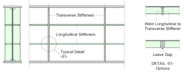
Longitudinal stiffeners are welded longitudinally along the length of the girder and are required to increase its bending strength. They may be either continuous, where they are welded to the transverse stiffeners, or discontinuous, where they effectively stop and start.
Continuous longitudinal stiffeners, if welded to the transverse stiffener may pick up stresses from the flange to which they are attached, so care must be taken to ensure that the stiffener is designed to accommodate these stresses.
Clarification will be required from the responsible engineer
Bearing Stiffeners
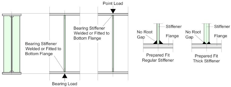
Bearing stiffeners are located at points of load to prevent buckling of the web, and sometimes the flange. They are usually quite substantial to take the compressive load, and as a rule-of-thumb are always thicker than the web. They are always located at bearing or jacking points where the girder is sitting on its supports, in which case the stiffener would be fitted or welded leaving no root-gap.
For continuous girders, the stiffener is not generally welded to the top flange because of the high tensile stress and consequential risk of fatigue cracking.
Top flange bearing stiffeners are located at point-load positions and work in the same manner, except that the stiffener is fitted or welded to the underside of the top flange.
Stiffener Sections
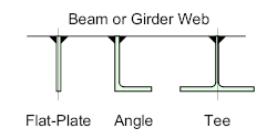
A variety of sections can be used as stiffeners, the most common being the Flat Plate, Inverted Angle and the Tee section.
However, with automatic girder construction, the majority are formed from flat plates, they are easier to fit and weld.
