This article was updated on the 24/06/2021
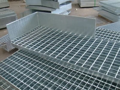
Open grid flooring is generally to be found in industrial applications where its open nature allows for the passage of light and air circulation. Also being open prevents the build-up of debris and standing water making it ideal for platforms and walkways when safety is a prime consideration. But it’s not limited to these applications, it can also be used for trench covers, screens and barriers.
There is no limit to the surface area that can be covered, provided it’s properly supported and fastened.
Image courtesy of: Anping Mengke Wire Mesh Manufacture Co., Limited
Open grid flooring can be supplied in a variety of materials including:
Steel – which can be used for most general applications and can be supplied plain or painted and galvanized for additional corrosion protection.
Stainless Steel – Where due to its natural resistance to corrosion, stainless steel grating is often used where contamination must be minimized – examples being, the chemical and food preparation industries.
Aluminum -Is often chosen as a lightweight option. As a material, aluminum is not as strong as steel but it is lighter. As a result, aluminum floor grating is popular in industrial environments where weight is a primary consideration.
It’s also regarded as having greater aesthetic appeal than other materials and is often chosen by architects for its aesthetic appeal
FRP – Fiberglass Reinforced Plastic flooring is molded into specific panel sizes which means the range is generally limited, therefore the steel framing plan must be designed with the floor panel layout in mind. It’s used mainly in areas of hazardous and flammable liquids and gasses where by its nature will not create sparks when in contact with other metallic objects. Additionally, being a plasticized resin, it’s non-conductive and non-magnetic making it popular in areas which are electrically hazardous and resistant to magnetic fields.
Much of what follows is focused on steel grating, but the general principles of setting-out and detailing will still generally apply
Grating Types
There are numerous types available on the market, but generally they will fall into one of 3 generic groups:
- Bar Grating
- Swage-Lock Grating
- Welded Bar Grating

Bar Grating
Bar Grating is manufactured from Flat bars which are set at right-angles to each other and interlocked by notching. If the bearer and intermediate bars are of the same depth, then both are usually notched. If the intermediate bars are of a lesser depth, then usually only the bearer bar is notched. They may be either welded or press-locked under high pressure
Swage-Lock Grating
With Swage –Lock grating the intermediate bars are inserted into pre-punched holes in the bearing bars and then swaged under pressure to lock the bearing bars in place grating forming a permanent locked structure.
Welded Bar Grating
With welded bar grating The bearer bars are grooved at the top to accept the intermediate bars which are then automatically resistance welded forming a permanent welded structure
Floor Panels
Floor panels are provided in standard spans (Lengths) which will vary between the various manufacturers, but generally, they will range between 300 mm and 1500 mm in increments of 100 mm. Non-standard spans can usually be accommodated – but for the detailer, it’s advantageous to try and stick to the standards.
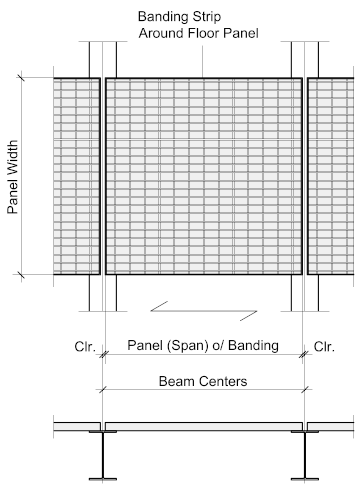
The span is measured over the bearer bars which will determine the centers of the supporting steelwork – each span should be supported, so a panel length of 1500 mm would require the supporting steelwork to be spaced at 1500 mm plus the nominal gap between panels which should never be less than 6 mm rising up to 20 mm. The gap should be equally spaced between the center-lines of the supporting members.
We'll look at the factors to determine the nominal gap later in this article.
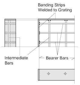
Floor panels are often Banded - banding is a flat bar strip welded to the outside of the panel with a size equal to that of the bearer bar. If the floor panel is banded, the length (span) of the panel must be given 'over banding'
*** Check with your local supplier if the standard lengths (spans) are given 'over banding' - if not, then the standard panel size will increase by the thickness of the banding strips.
Setting-Out Floor Grating - A Case Study
Floor grating is often ignored when setting out the steelwork framing plan – meaning that the panels have to be laid on steelwork which is not ideally placed which can unnecessarily complicate the floor layout.
The correct and best way to do this is to take the flooring into account from the beginning – to illustrate this point, we’ll look at a hypothetical case study of a simple, but busy, maintenance platform supporting two cylindrical vessels with a stairway leading from the floor below. For good measure, another opening has been added for no good reason except to demonstrate the principles of laying out the floor panels.
The one thing to keep in mind when setting our flooring is to keep the bearer bars in the same direction for the entire floor. This not only makes the setting-out simpler but it looks better. To have the bars criss-crossing over a floor area is unnecessary, looks terrible, and is unprofessional.
To this end, the platform framing has been set-out assuming the panels will span from left to right along the X axis – the dimension X represents supporting beam centers which will equal the panel span plus the gap between panels, for example, if the panels are to be 1500 mm and the gap between them 10 mm, then X will equal 1500 + 10 = 1510 mm. The dimension X can be anything – in fact they don’t all have to be equal provided they do not exceed the maximum recommended panel span.
For the purposes of this exercise the location of the vessels and stairway are not that important – again, they may be placed anywhere within the platform, the general principles will be the same.
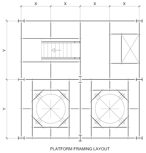
When laying out any structure, whatever size or scale, symmetry is always beneficial – it will enable the detailer to standardize member sizes, connections, and will reduce the number of different beam lengths – but a symmetrical structure does not always translate into a symmetrical floor layout. This will depend on the floor openings and position and orientation of the columns.
Once the framing plan has been determined, we can see what the flooring layout will look like.
Overlaying the Floor Panels
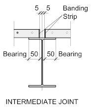 The first thing you notice when looking at the floor panel layout is that it’s uniform – this is due to the support steelwork across the X axis being set out to a constant spacing. In this example, the beams are equally spaced (at 1510 mm. to suit the standard panel). Also, the bearer-bars all span in the same directions – with a little care, it will be possible to line up the bearer bars, which looks especially good.
The spacing between the panels (in this example) has been set at 10 mm. equally spaced about the centers of the supporting steelwork. This will allow for necessary adjustment on site – insufficient clearance may cause problems with installation and can be very difficult to fix on site. The nominal gap is determined by the bearing of the floor panel on the supporting steelwork – which should be somewhere in the region of 50 mm. This is to compensate for any misalignment of the support steelwork.
Uniformity offers many advantages:
Firstly, it means the grating panels will all be of the same width – this makes things so much easier for the workshop, not to mention the on-site erection team.
Secondly, with careful placement of the equipment and stairways within the structure many of the panels, particularly the shaped ones, can be kept the same.
As can be seen from the floor layout below, the panels surrounding the vessels are basically all the same. The differences between 1 and 2 relate to the orientation of the columns, the suffix X after the part number means the panel is handed. Handing means the panel dimensions are the same but the upstand of the Kick-Plate will differ.
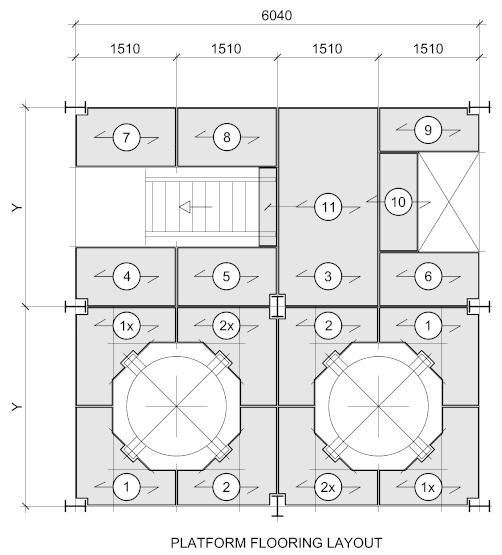
As the floor panels have been set out symmetrically, it means the outer panels will begin and end on the centre-lines of the beams leaving the outer part of the support beam flange available to mount the handrail. This is always the simplest, neatest and most efficient way to set out the floor panels.
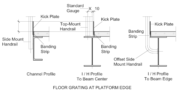
If the floor grating is to extend to the outer edge of the beam, it may require a special panel or alternatively, the support steelwork will have to be adjusted accordingly.
If the support steelwork is a channel or angle, the grating will always extend to the heel of the member.
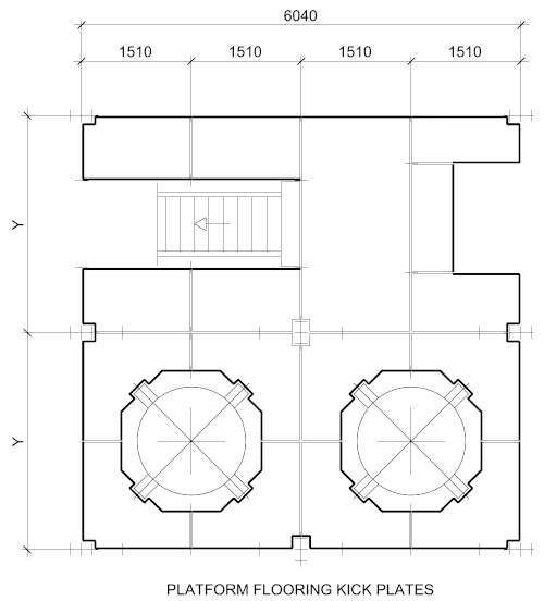
Kick Plates
Kick Plates are placed around the perimeter and inside openings of floors to prevent items or debris being kicked off the floor to the level below possibly causing injury.
They also prevent personnel trapping the foot between the floor grating and columns or vessels passing through.
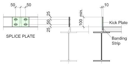
The Kick Plate is welded to the banding bar and should extend at least 100 mm above the floor - the weld only needs to be an intermittent fillet.
Though not always necessary, the joints between the kick plates, which will correspond to the grating joints, may be connected using splice plates.
Fixing the Grating Panels
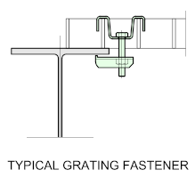 Open grid flooring may be fixed to the supporting steelwork by either site-welding or using clips. Site-welding can be time-consuming and often uncertain and leaves no room for later adjustment. Using proprietary clips is by far the most common and is recommended for most applications where the floor grating is not an essential component of the Horizontal Stabilizing System.
There are numerous types of clips on the market and it's recommended that they be purchased from the grating supplier to ensure compatibility.
To calculate the number of clips required, it's recommended that there be a minimum of 4-clips per m2 with at least 4 clips per panel. For longer panels, clips should be provided at the intermediate support beams.
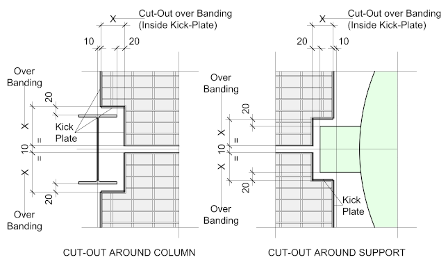
Typical Cut-Out Details
The cut-outs around columns should have sufficient clearance greater than the gap between the floor panels. In this instance, with a panel gap of 10 mm - the clearance gap should be approximately 20 mm.
