Introduction to Crane-Beams and Girders
Crane-Beams of Girders, are a stand-alone structural component, in that unlike conventional beams and Plate-Girders they have to withstand high lateral forces generated by the movement of the crane gantry along the track, and the cross-movement of the trolley across the crane gantry. Additionally, they have to resist the longitudinal forces generated by the acceleration, travel, and braking of the crane gantry on the track.
Consequently, the crane-girder must be designed to resist bending, web-buckling, and top-flange deformation due to the eccentric loading of the crane-wheels on the crane-rail. For deeper crane-girder sections (above 400 mm.) it will be necessary to restrain the top-flange back to the building column by means of a tie-back or continuous surge-girder to resist the lateral forces.
Stiffening the crane-girder against deformation is achieved by web and flange stiffeners positioned at intervals along the girder length (See Crane-Girder Stiffening), while lateral support is achieved by means of ‘Tie-Backs’ or ‘Surge-Girders’ which restrain the girder top-flange against the building column (See Crane-Girder Top-Flange Restraint), therefore, when designing crane-girders the interaction between the girder and the structure itself must be taken into consideration.
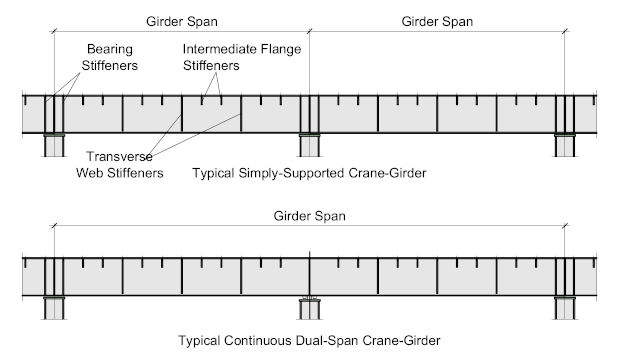
Crane-Girders may be either simply-supported, semi-continuous, or continuous, but due to the complexities in design of the latter, combined with the difficulty of erection and alignment, simply-supported crane-girders are the de-facto standard.
The simply-supported girder effectively spans between column-to-column with the girder ends bearing on the column cap-plate or Corbel. (see Crane Columns)
Typical crane Girder Sections
Typical crane-girder sections include:
- Standard Hot-Rolled beams section which would typically be used for short-span – lightly loaded applications.
- For slightly heavier applications a standard hot-rolled section with an inverted channel cap may be employed to provide support to the top-flange and resist lateral loading from the crane-wheels.
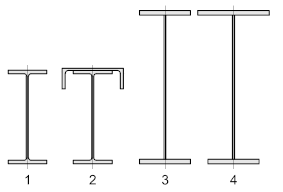
Though the channel-cap will effectively stiffen the top flange it’s of limited value in providing the necessary lateral rigidity.
- Symmetrical Plate-Girders are used for heavy duty wide-span applications which can be selected and designed for all applications
- Monosymmetric Plate-Girders typically comprise of a wider and thicker top-flange used in very-heavy duty applications
The selection and design of the Crane-Girder is dictated by the Duty-Classification of the crane:
Crane-Girder Support
Typically, crane-girders are supported by seating the bottom-flange onto the supporting column.
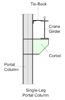
For light-duty applications the crane-girder may seat onto a bracket, or corbel, attached to a single-leg portal column, the capacity of such connections is limited to the high moments induced into the column.
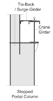
To increase the capacity for portal-frame structures, a ‘stepped’ portal column is often used, whereby the crane-girder is seated onto the cap-plate above the flange of the column. The reduced section is continued to support the roof rafter.
For heavy-duty cranes, twin-leg columns are used whereby the crane girder is supported by seating onto the column cap-plate of the crane-leg. The roof-leg is connected to the building column and extended to support the roof rafter or truss.
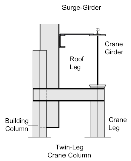
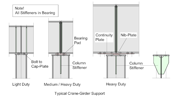
There are numerous ways to support the crane-girder onto the column-cap which are determined by the design considerations, for the purposes of this exercise we will look at 3 options, which between them represent a fairly typical cross section.
In each case the girder-ends are bolted to the column cap-plate using 4-bolts (or to the top-flange of the cantilevered corbel).
The ends of the girders are subject to longitudinal movement resulting in the gap between the abutting girders increasing and decreasing when one or both are under load. As the crane girders must be free to rotate in this manner longitudinal continuity for the horizontal load path is maintained through the connection.
For light-duty applications, the crane-girder may be bolted directly to the column cap-plate with bearing stiffeners aligned to the supporting column flanges ensuring an efficient load transfer into the column. Horizontal continuity is achieved through the column cap-plate.
For Medium / Heavy-Duty applications, the crane-girder may seat onto a bearing-pad to help reduce any eccentric loading onto the column which must be small enough to ensure the girder is simply-supported. The bearing-stiffeners are located at the girder-ends and a central stiffener is located in the column web.
This stiffener should be continuous, meaning a slot should be cut into the column web with the stiffener inserted and welded to improve the bearing capacity of the column.
For heavy-Duty applications, the girder ends may sit on a nib-plate which sits inside the bolt-group and is not directly bolted through the girder bottom-flange. Horizontal continuity is achieved by means of a continuity-plate which must be thin enough to ensure it does not offer resistance to bending, but still allow a continuous path for the longitudinal forces to travel.
Girder Stiffening
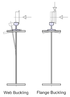
Crane-Girders are subject to horizontal and lateral forces which are applied at or near to the top-flange. The horizontal movement of the crane wheel, which can be as much as 50 mm creates an eccentricity on the top-flange vertical loading which creates a torsional moment on the top-flange. This can result in torsional web-buckling and / or flange buckling. Consequently, the top and bottom flanges act independently and are designed as such.
These dynamic loads are cyclic responding to the movement of the crane, and the magnitude of these loads is a function of the particular Crane Classification.
This repeated cyclic loading means that the crane-girder is subject to fatigue, which for extra-heavy-duty cranes can become the dominant design consideration.
To resolve these issues, the top-flange of the crane girder needs to be stiffened and restrained. Stiffening is achieved by a combination of flange and web-stiffeners placed at intervals along the girder length, while restraint against the lateral loads is achieved by means of Tie-Backs or Surge-Girders, tying the crane girder to the building structure. (Crane-Girder restraining options are discussed later in this Article )
Stiffening Options
Top-Flange Stiffeners
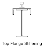
Where a standard hot-rolled beam section is used, the top flange is usually reinforced by means of an inverted channel section welded to the top flange of the beam. This solution will give additional support to the top-flange and provide some resistance to the lateral loading from the crane wheels. However, this configuration applies to light / medium applications as the channel is of limited value in providing the necessary lateral rigidity for heavy-duty cranes.
The inverted channel however lends itself to convenient Tie-Back options, which are discussed later in this article
Top-flange Stiffeners – Welded Plate-Girders
Plate-girders present a different set of considerations:
The repeated cyclic loading on the top-flange means that the weld between the top-flange and the web is particularly susceptible to fatigue, consequently, it’s inadvisable to use fillet-welds because of the difficulty in ensuring full flange to web contact. Full-penetration groove welds should be used.
This criterion does not apply to the bottom-flange, however it’s general practice to employ groove-welds in both top and bottom flanges at the fabrication stage to avoid them getting crossed-over later in the fabrication process.
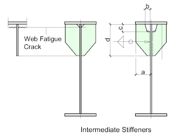
The same considerations must be taken into account when looking at the intermediate flange stiffeners. The top of the stiffener may or may not be welded to the underside of the top-flange, but whichever option is specified the stiffener must be fitted for full bearing to reduce the risk of weld cracking due to fatigue. ‘Fitting’ a stiffener means that the top of the stiffener should be cut true and square to ensure full contact between the mating-faces.
For this same reason, shallow ‘Snipes’ should be avoided at the Flange /Web intersection – an ‘engineered’ cope should be used – See Illustration below.
Intermediate, or ‘stub’ stiffeners are generally used where considered to be necessary, they should be placed one or two between the transverse stiffeners or spaced equally to the pitch of the rail clips.
| a = Stiffener Width
b = 0.5 x a c = 0.1 x the Girder Depth d (min) = 2.5 x a / or 0.2 x the Girder |
Transverse Web Stiffeners
The Transverse Web-Stiffeners are placed at regular intervals along the length of the girder.
In simply-supported crane -girders (supported at each end) the transverse stiffener should not be welded to the bottom-flange as Fillet-Welds transverse to the tension flange are prone to fatigue failure. The stiffeners should be kept clear by a distance of not more than - 4 x the girder flange thickness. The top of the stiffeners may or may not be welded to the underside of the top-flange. If not welded, they should be fitted to the underside of the flange for full-bearing.
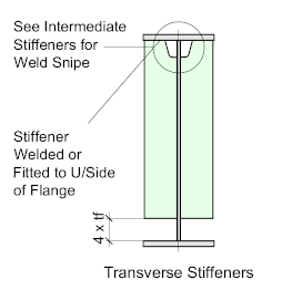
The longitudinal welds on the girder web may be intermediate Fillet-Welds for light to medium duty applications, while for heavy-duty, they should be continuous Fillet-Welds returned at the top and bottom.
For continuous crane-girders, the same general conditions apply, except that the stiffener should be fitted to the underside of the top-flange, but not welded. The stiffener may or may not be welded to the bottom-flange.
The weld access hole, or cope, should have adequate depth so as not to allow fatigue cracks in the web (as for intermediate flange stiffeners).
Bearing Stiffeners
Bearing stiffeners are placed at the ends of the crane girder and should be fitted to the underside of the bottom flange for full bearing. In the event of a continuous girder, the stiffeners should be placed at the point of bearing.
For stiffeners up to 12 mm thick, Fillet-Welds may be used, but note that with the use of Fillet-Welds, full bearing onto the flange may be difficult to achieve. For stiffeners greater than 12 mm thick, prepared welds should be used with at least 90% penetration.
The stiffener should extend and be fitted to the underside of the top-flange and be Fillet-Welded, except in the case of continuous girders, where they should be fitted only
Where the ends of the girders abut over a column, the squareness of the girder-ends must be within close tolerances. Rail-Joints usually occur at this point and any misalignment or differences in level would produce a discontinuity that will adversely affect the wheel wear and rail fixings.
Bearing Stiffeners should be located immediately above the point of bearing. For light to medium duty applications, this may be in-line with the flanges of the supporting column placed outside of the fastening bolts.
For heavier duty applications, the bearing stiffeners are often located at the girder-ends, allowing sufficient space for the vertical Fillet-Weld. In such instances a column stiffener should be welded into the column wen to ensure full bearing capacity into the column. This stiffener should be continuous, i.e. a slot cut into the column web allowing fitment of the stiffener. (See Crane-Girder Support)
The fastening bolts are located outside of the bearing stiffeners to ensure the girder is simply-supported.

