In this example, we show an all-welded lightweight girder truss. Its formed from single angles with alternating lacing members.

For All-Welded trusses formed from angles, the work points should be established from the centroids of the members. In order to achieve maximum weld contact between the members, the diagonal lacing members are located on the far-side of the chords.

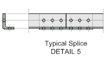
To splice a truss is never desirable but sometimes it's unavoidable. In the case of this particular truss type, it's unlikely to be required - but if it is, the general rule is that the top and bottom chords should be staggered equally about a vertical truss member.
End Support Options
Following on from the Introduction, below are some examples of typical truss support options:

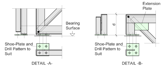
Detail -A- illustrates a typical seating connection with a base-plate welded to the bottom chord of the truss. The base-plate and bolt hole pattern should be set equally about the heel of the angle which in turn, should be the center of the support member.
Detail -B- shows a typical top chord seat. The leg length (d) should be such as to allow clearance for the diagonal lacing member - this will depend on how the truss will be supported i.e on a column cap or horizontal beam. An extension plate welded to the toes of the angles will be required to ensure sufficient weld to the component members and offer stability to the leg.
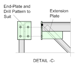
Detail -C- shows a typical end-plate connection connecting to a column or another truss. As with the previous detail, an extension plate will most likely be required to ensure sufficient weld fro the component members.
The heel of the angle chord should align with the center of the column and the bolt-hole gauge should be in accordance with the recommended or 'workable' gauge of the column.
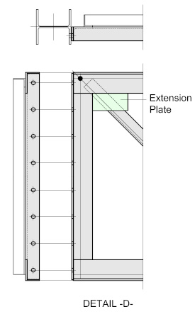
Detail -D- illustrates a fairly typical connection to a column. The vertical truss member runs the full depth of the truss and will work for almost any truss configuration (see Introduction).
As with the precious detail, the heel of the angle chord should align with the center of the column and the bolt-hole gauge should conform to the recommended or 'workable' gauge of the column
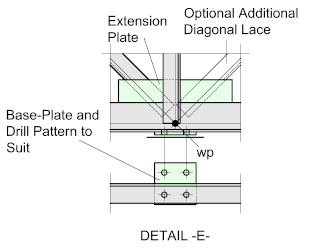
Detail -E- shows a typical connection for a cantilevered truss. A simple base-plate is welded to the underside of the bottom chord which should align with the vertical truss member. Sometimes (depending on the design requirements) an additional diagonal lacing member may be required to concentrate the load to the column cap.
