
In this example, we show an all-bolted light/medium girder truss. It may be formed from either single or double (battened) angles.
The members are connected using gusset-plates.

For all-bolted trusses formed using angles, the work points may be established from the centroids or centers of the members. Technically, he correct way is to use the centroids but as the holes are commonly set out on the center-line of the lacing members, many detailers prefer to use these center-lines as the setting-out points. It will inevitably result in some eccentricity at the joints, but these are usually relatively minor and should be able to be accommodated.
As usual, just check this out with the responsible engineer.

Sometimes, a splice may be necessary, in such cases they can be easily accommodated by incorporating them into the gusset-plate joint.
Splices should ideally be located so that they are staggered equally about a vertical truss member.

End Support Options
Below are some examples of typical truss support options:

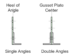 The following typical examples assume the truss has been formed from single angles. In this event, the heel of the angles (top and bottom chords) should ideally be set out at the center-line of the support, which may be either a column or beam. Should double (battened) be used, the truss should be set-out at the center-line of the truss.
Detail -A- illustrates a typical seating connection with a shoe-plate welded to the bottom chord of the truss. The shoe-plate size and drill pattern for the bolts should align with the means of support.
Detail -B- shows a typical top chord seat. The leg length (d) should be such as to allow clearance for the diagonal lacing member - this will depend on how the truss will be supported i.e on a column cap or horizontal beam.
As with Detail -A- the shoe-plate size and drill pattern for the bolts should align with the means of support.
Detail -C- shows a typical end-plate connection connecting to a column or another truss. As with the previous detail, an extension plate will most likely be required to ensure sufficient weld fro the component members.
The heel of the angle chord should align with the center of the column and the bolt-hole gauge should be in accordance with the recommended or 'workable' gauge of the column.

Detail -D- illustrates a fairly typical connection to a column. The vertical truss member runs the full depth of the truss and will work for almost any truss configuration (see Introduction).
As with the precious detail, the heel of the angle chord should align with the center of the column and the bolt-hole gauge should conform to the recommended or 'workable' gauge of the column
Detail -E- shows a typical connection for a cantilevered truss. A simple shoe-plate is welded to the underside of the bottom chord which should align with the vertical truss member.

