Here we'll look at typical horizontal bracing connections connecting to beams and columns. They include both welded and bolted gusset plates.
For information on bolt hole edge-distances and spacing refer to Bolt-Hole Spacing and Edge-Distances
Welded Gusset Plates to a Beam
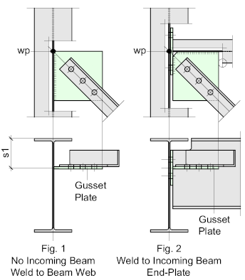
Fig’s 1 and 2 illustrate typical welded Gusset-Plates.
Fig. 1 – shows the Gusset Plate shop-welded to the web of the supporting beam, this is the most common connection type where there is no incoming beam, it’s simple and economical.
Fig 2 – illustrates the Gusset-Plate welded to the web and End-Plate of the incoming beam. This represents the most common and economical bracing connection arrangement where an incoming beam is present.
This connection type will work with Cleat or End-Plate connections
Welded Gusset-Plates generally are the most compact, efficient, and relatively simple to fabricate and erect. The Gusset-Plate itself, may be either square, shaped, or profiled, depending on preference.
For more information on these options – refer to Gusset-Plates
Bolted Gusset Plates to a Beam
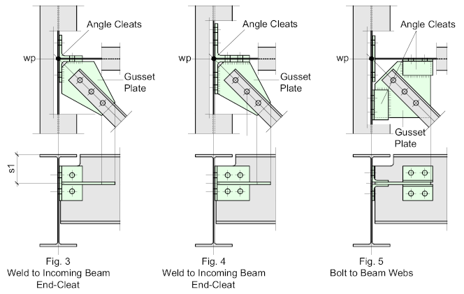
Fig’s 3, 4, and 5 illustrate typical bolted Gusset-Plates to a beam
Bolted Gusset-Plates always work with the incoming beam, the only exception would be if the bracing system is a retro-fit, and even then, it may prove difficult to justify especially when considering costs in both fabrication and erection.
Fig 3 – Shows the Gusset-Plate welded to the End-Cleat of the incoming beam, it’s a very neat and compact arrangement and will work for most end-cleat beam-end connections. One consideration if a ‘standard’ cleat is used is to check that there is sufficient weld at the joint to satisfy the design requirements, if not, then consider using a larger ‘standard cleat’ as illustrated in Fig 4.
For more information on Standard Cleats – Refer to: Flexible Connections - Cleats
Fig 5 – illustrates the use of a fully bolted ‘Wrap-Around’ Gusset-Plate which works independently of the beam connection.
This type of joint is usually applied to Welded End-Plate connections.
Connecting Horizontal Bracing to a Column with Work-Points set to the Column Flange
As can be seen, horizontal bracing very rarely connects directly to a column, instead, it connects to the incoming beam,
Ideally, the work points should be set to the column center, but it's fairly common practice to set them at the column flanges provided the eccentricity of the connection does not cause any problems. The advantage with this type of connection is that the gusset plates become neat and compact and may be used with either end-plate or end-cleat connections.
Fig. 6 illustrates such a connection where the incoming beam connects to the column by means of an end-plate, allowing for the gusset plate to be welded to both. This is a fairly straightforward connection to detail and fabricate - and easy to erect.
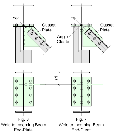
Fig. 7 shows a similar connection where the beam connects to the column by means of end-cleats. In this situation, the gusset plate is welded to the cleat and not the beam - the cleat is then bolted to both the incoming beam and the column, making it effectively an all-bolted connection.
This will never be as effective as the first option as the welding is reduced (unless a large unequal leg angle is used for the cleat) and it can be tricky to fabricate and erect. But this is a good option if the bracing is to be retro-fitted into an existing structure.
Connecting Horizontal Bracing to a Column with Work-Points set to the Column Center
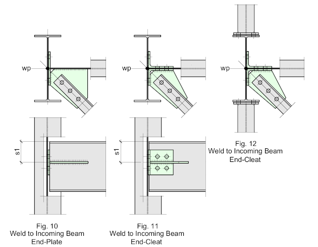
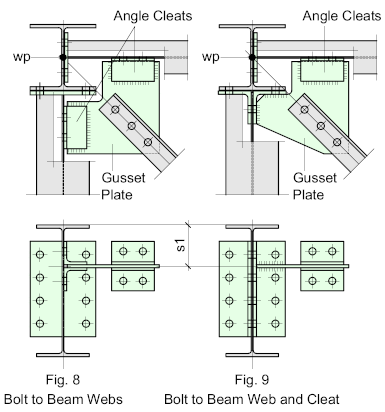
Sometimes, it’s essential the work-point intersects at the center of the column, in which case it will most likely require the use of a ‘Wrap-Around’ Gusset-Plate as illustrated by Fig’s 8 and 9.
These connections are usually quite complex and require careful detailing.
They are by necessity, all-bolted and are fabricated separately from the connecting beams and columns. They are site-bolted to the webs on the incoming beams by means of cleats which are usually welded to the Gusset-Plate. The cleats may be fitted to either the top, bottom. Or both faces of the plate, bearing in mind, that the cleat on the bottom face of the plate can sometimes be difficult to access.
The following typical examples have been added to show it's not all bad news. Up to this point, the examples have assumed the column section is a standard 'H' but if it's a beam of girder section it may be possible to maintain the center of the column as the work-point without any of the complications mentioned earlier.
Fig 10 – illustrates the configuration generally applied to End-Plate connections by bolting the Gusset-Plate directly to the webs of the incoming beams. This configuration applies to -I- section columns
Fig 11 – shows a possible configuration for End-Cleat connections, where the plate is welded to the inside face of the cleat.
Fig. 12 - just illustrates that incoming beams connecting to the flanges of the column will have little or no affect.
