Anchor Bolts range from those required for normal fixing of concentrically loaded columns to those subject to uplift, shear and moment forces.
The standard diameters suitable for use are M20, M24 and M30. These sizes match standard nuts while for bolts M36, M48, M56, M64 and M72 - round bars of the next larger standard size are used and turned down to the required thread diameter.
Anchor Bolt Tolerances
When positioning anchor bolts there can be significant construction differences between the steel and concrete so greater tolerances should be allowed exceeding those for normal steel construction.
Grout clearances, overlength allowances on bolt projections and bolt clearances in base plate holes should be sufficient to allow for bolts that are out of tolerance and inaccurate levels of concrete. generally, Anchor Bolts should be within 3 mm of their required position and the top of concrete and bolts should be within 5 mm of their required level. Consequently, Anchor Bolts should be positioned with allowance for some adjustment.
Anchor Bolt Types
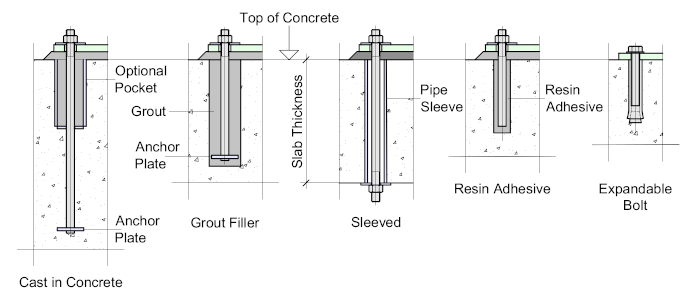
Anchor Bolts come in various forms which are illustrated below:

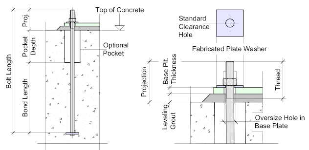
- Cast in Concrete - which is probably the most widely used. The tensile resistance of the bolt is developed by the bond between the bolt shank and the concrete plus the bearing resistance of the anchor plate. The pocket is formed by placing a pipe at the top of the concrete of approximately 75 mm diameter for M20 and M24 bolts rising to 100 mm diameter for M30 bolts. The length of the pocket is usually 25 - 30% the length of the bolt. This will allow for sufficient adjustment.

The grout thickness is usually between 25 and 30 mm which must be taken into account when considering the bolt projection.
The bolt projection should make allowance for the grout thickness + the base plate thickness + the nut and/or locknut.
The washer is usually fabricated to allow for the Oversize Hole in the base plate while the bolt-hole is a standard Clearance Hole.
The anchor plate is fabricated from plate and welded at the bottom of the Anchor Bolt in accordance with the sizes listed in the table.
As an alternative to the anchor plate, the bolt may be bent through 90° forming an L Bar. The length of the L should not be less than 100 mm.

|
Anchor Plates |
|||
|
Bolt Dia. |
Plate Size | Thickness |
Weld |
|
M20 |
70 x 70 | 12 |
6 |
|
M24 |
80 x 80 | 14 |
6 |
| M30 | 110 x 110 | 14 |
6 |
Other Anchor Bolt types include:
- Grout Filler - which is used in situations where there is minimal uplift and moment reactions. In this case a pocket is cast into the concrete and the bolt is dropped in during erection. The anchor plate will offer some assistance but the bond is limited to the grout.
- Sleeved - this is usually provided when bolting equipment or machinery to its concrete base. A pipe is cast through the concrete providing access from the top and bottom. An access pocket should be provided at the bottom to allow access for tightening the bolt. The big advantage with this arrangement is that it allows for regular maintenance checks and adjustment where necessary - particularly on rotating or vibrating machinery.
- Resin Adhesive bolts are used for light duty applications allowing the bolt to be placed with the base plate in position.
- Expandable bolts. like the Resin bolts, allow the bolt to be placed through the base plate. A hole is drilled into the concrete to the length of the bolt which is the hammered into the hole forcing the conical wedge to expand the bolt.
Grouping Bolts
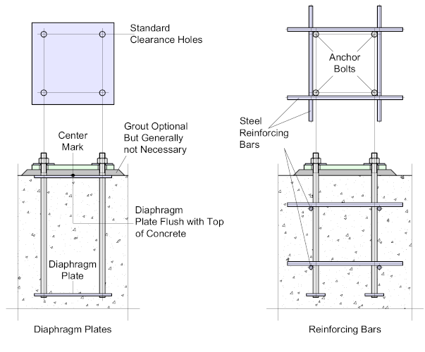
To aid with the alignment of bolts, especially on large columns it can be advantageous to group the bolts, forming a Cage.
There are a number of ways this can be achieved but the most widely used is the Diaphragm and tying the bolts together using Reinforcing Bars

The Diaphragm is a flat plate which is pre-drilled to accept the bolts - the diaphragm plate(s) may be placed anywhere along the length of the bolts, but usually at the top and bottom. The bottom plate increases the bearing resistance of the bolts while the top plate may be situated level with the top of concrete providing an accurate landing for the base plate. A survey center-mark is placed at the center of the diaphragm for alignment.
If the plate is to be used to provide a flat surface for the base plate - then the concrete must be poured to a high level of accuracy - if this cannot be guaranteed, a levelling grout may be added.
The second option os to create a Cage - there are numerous ways to do this but the most widely applied is to weld reinforcing bars to the bolts which will not only keep the bolts together, but will substantially increase the bond.
Alternatively, the reinforcing bars may be wrapped around the bolts or integrated into the overall reinforcing pattern for the concrete.
