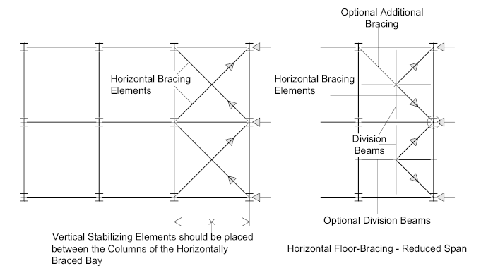
Horizontal braced frames are usually found in industrial type structures, where due to their open nature Composite Floors are not an option. Lateral force distribution is achieved by, what is effectively a Horizontal Triangulated Girder or Truss. The bracing system may be configured in any number of ways, depending on the limitations and/or the requirements of the structural design.
Horizontal Bracing members may be in tension or compression, depending on how they’re configured, but its more common for them to be designed as compression struts.
Long bracing members may be subject to vertical bending, or Lag, under their own weight which can make them difficult to erect – and as they are likely to be designed as compression members, their effectiveness may be reduced. There are basically two ways to overcome this:
- Stiffen the bracing members by making them heavy enough to resist the bending or lag.
- introduce secondary ‘division-beams’ beams in order to reduce the bracing member span.
But whichever way the bracing elements are configured, the bracing system should be located so that it can effectively distribute and transmit the lateral forces to the vertical stabilizing elements of the structure
Non-structural horizontal bracing is often employed by fabricators and erectors to ‘square-up’ the structure during erection, and sometimes on pre-fabricated modules for transport.
Such bracing is usually fitted to the bottom flanges (where practical) so that it does not interfere with any permanent steel that needs to be installed. After the floor has been constructed, it may be removed, or left in place provided it doesn’t interfere with non-structural elements such as service pipes or air-conditioning routed under the floor.
Horizontal Braced Frames in Single Storey Structures
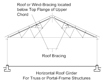
On single storey steel structures, such as ‘Portal-Frames’ horizontal stability is achieved by means of a ‘wind or roof-girder’ which is situated at roof level and integrated into the roof structure.
On Portal-Frame structures the roof bracing is fixed to the roof girders between the column bays and just below the top flange so as not to interfere with the roof purlins. As with other forms of horizontal braced-frames, the bracing elements should be located so that they can effectively distribute and transmit the lateral forces to the vertical stabilizing elements of the structure.
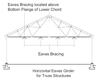
Such structures may require additional ‘Eaves-Bracing’ located at the eaves of the truss, which, as with roof bracing, it should be located to transmit the lateral forces to the vertical stabilizing elements.
Auxillary Wind Girders
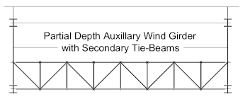
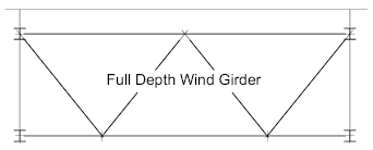
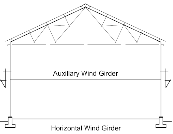
On tall single storey structures and additional wind girder may be installed at each gable-end to work in conjunction with the roof girder. Typically, such girders are located approximately half-way up the gable-end columns. But care must be taken to ensure that the girder will not interfere with any gable-end access requirements, and will not inhibit ‘lifting-access’ for the overhead crane (if installed)
