Typical Examples
Here we’ll look at some typical examples of a hollow section beam to beam connections. The first examples illustrate a hollow section beam bolted to a hollow section supporting member – as mentioned in the Introduction, this is not a widely used configuration and are used in mainly single-storey lightweight structures.
 Figs. 1 and 2 illustrate examples where the supporting and incoming beams are of the same depth allowing the use of end-plates fastened with Through-Bolts. Fig. 1 shows a condition where angle cleats are welded to the top and bottom faces of the supporting member to which the incoming beam, fitted with an end plate, is fastened. Fig. 2 shows a similar arrangement with the cleats substituted with a plate welded to the mating face of the supporting beam. In both cases, the incoming beam has a Closed End.
Fig. 3 shows an example of a similar connection using angle cleats providing an Open End
(For more on Open and Closed Ends refer to the Introduction)

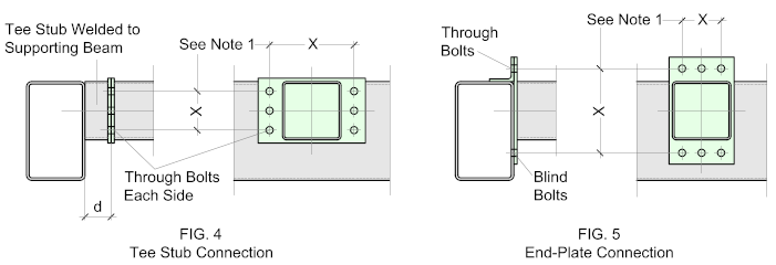
More often than not, the beams are not always the same depth which results in a more limited range of options. Fig. 4 shows one of the most widely used solutions which is to weld a Tee Stub to the supporting beam which would be the same profile as the incoming beam. The length of the stub (d) should be sufficient to allow access for placing the bolt. This option may make use of end-plates with Closed Ends (as illustrated) or angle cleats with Open Ends allowing for the use of Through Bolts (See Fastening Options)

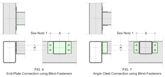
Fig. 5 illustrates a typical connection using a combination of Through and Blind-Fasteners with a cleat welded to the top face of the supporting beam while the end-plate or cleat is fastened at the bottom using Blind-fasteners.
Blind Fastening Options
Connections using Blind Fasteners are neat and compact much favored by architects for their discrete pleasing appearance. As with all Blind fastening options they require a high level of fabrication accuracy and some skill in erection.

Fig. 6 shows a typical end plate connection bolted directly to the mating face of the supporting beam, while Fig. 7 shows a similar connection using angle cleats. The end-plate will result in a Closed End and the angle cleats will provide an Open End.
Connecting Open Sections
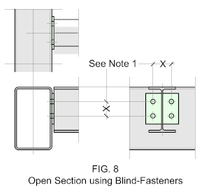
Connecting an open section to a hollow section supporting beam is similar to that when connection all hollow sections. The one difference is in the bolt pattern of the end plate - for more information on this see Note 1.
Note 1.
For more information on the bolt patterns including, bolt diameters, bolt-hole spacing, and edge distances go to Bolt Patterns


What is the best way to splice an I-Beam to extend its length
For I Beams you can use a bolted or welded splice. You’ll find information here:
https://structuraldetailer.com/welded-beam-splice/
https://structuraldetailer.com/bolted-beam-splices/