The Vertical Braced-Frame is the most straightforward and efficient vertical stabilizing system. It’s fairly straightforward to resolve, and equally straightforward to fabricate and erect. Braced frames are flexible in the sense that they can be adapted to suit almost any conditions and a wide variety of load combinations.
Bracing is also the most economical stabilizing option in that the bracing elements carry the lateral loads while the beams and columns are required to transmit axial loads only. Consequently, the connections between the beams and columns are ‘nominally pinned’ thus simplifying the design and construction.
The bracing system transmits the lateral loads by means of triangulation, where the braced-bay is effectively a vertical triangulated truss which should extend the full height of the building.
The vertical bracing system should be located so that it can effectively transmit the lateral forces from the horizontal stabilizing system.
The disadvantage of vertical bracing is that it may impede external openings in the building, particularly in commercial or residential buildings where the façade demands windows or a glass curtain-wall, which in some instances, may spoil the aesthetic properties of the structure.
However, some post-modern structures have overcome this disadvantage by incorporating the bracing into the overall aesthetic.
Bracing Patterns
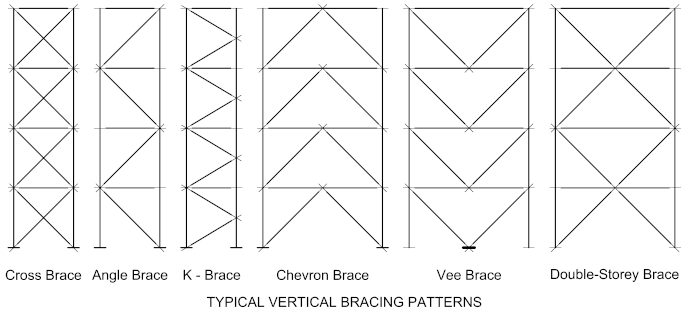
Vertical bracing is generally configured to well-defined patterns, which are illustrated below. The choice of pattern is dependent on the design philosophy and the nature and intended use of the structure.

Tension and Compression Elements
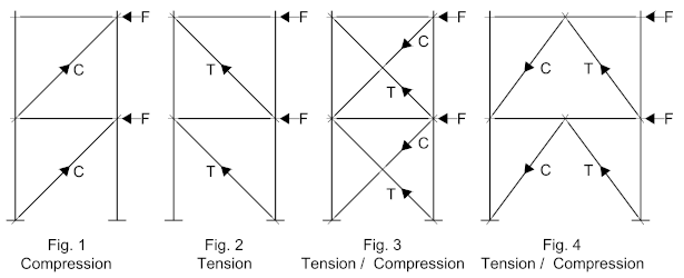
Bracing members may be either in tension or compression, depending on the direction of the lateral force and the configuration of the system.
A Tension member is effectively being ‘stretched’ and would be selected according to its ‘yield’ properties. Steel is very efficient in tension and consequently a tension member tends to be considerably smaller, while the connection to the structure, would likewise be lighter. A tension member is also referred to as a ‘Tie’
A compression member, or ‘strut’ must resist axial compression and therefore would generally be heavier to prevent buckling while the connection to the structure must be designed to resist the compressive force. If a Gusset-Plate is used to connect the bracing to the structure, it should be as compact as practical in order to resist out-of-plane buckling as a result of the compressive force.

Fig 1 - Illustrates a simple structure with the bracing members in compression
Fig 2 - Illustrates the same structure with the bracing elements in tension. Whether they are in tension or compression is dependent on the direction of the lateral load, if the load direction is reversed, so the tension and compression members will reverse., so in both cases the bracing elements would both be designed for compression, being the worst case.
Fig 3 - Illustrates a ‘Cross-Brace’ where the bracing elements work in both tension and compression, in such cases the compression and tension elements balance each other out irrespective of the lateral force direction, consequently, the compression elements are largely ignored in favor of the tension brace. This configuration is by far the most efficient and will work for most load conditions.
Fig 4 - Illustrates a ‘Chevron’ pattern, where like the ‘Cross-Brace’ the bracing elements work in both tension and compression, except in this instance they work either in tension OR compression, depending on how the structure has been designed. If they have been designed to work in compression the bracing elements will be heavier and the connections more substantial.
Concentric / Eccentric Bracing Patterns
Concentric Bracing
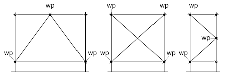
Concentric bracing is by far the more common bracing system, being ‘concentric’ implies that the ‘centroids’ or centers-of-gravity of the component members which include the beam, column, and bracing member, intersect at a common Work-Point or ‘Node’ This configuration ensures the most efficient load-path for conventional wind-brace structures and may be configured for either tension or compression. The bracing members are usually connected to the structural elements by means of Gusset-Plates, which are covered in more detail later in this series.
For particularly large members you can deviate from this general principle by aligning the work-points to the flanges instead of the centroids – this will be looked at when we examine the setting-out principles for vertical bracing later in this series.
The following illustrations show typical concentric bracing configurations

Eccentric Bracing
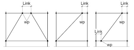
Eccentric Vertical bracing patterns are commonly used is seismically active regions, the patterns are similar to that of single and Chevron patterns, except that the bracing members do not intersect at a common ‘node’ point on the beam.
The offset between the theoretical work-point and the actual work-point is known as the ‘link’ which is designed to absorb seismic energy through plastic deformation. Such bracing patterns are usually configured to work in compression and are more commonly found of rigid frame structures.
Compression elements (struts) are covered in more detail later in this series.

