Multi-Storey structures generally require that the columns be ‘spliced’ in order to extend their length for the full height of the structure. Splices may be either bolted or welded and its always assumed that welded splices are ‘shop-welded’ while bolted splices are ‘site-bolted’. It is possible to call for a site-welded splice, but making such a connection can be difficult, time consuming, and often risky, and as such should be avoided. Splices should be designed so that the column is effectively continuous and therefore should be able to transmit the full bearing load throughout its total length.
They must also resist any horizontal moments that may be incurred by lateral displacement, consequently, column splices are generally designed to be ‘moment-resisting’. The column splice should always be placed as close to a point of lateral restraint as possible, and away from points of maximum deflection.
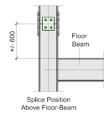
The individual column length is always determined by the spacing of the floors, with the column splice ideally located approximately 600 to 1000 mm above the floor. This means that the floor-beam connections will always be made beam-to-column and not, if the splice is below the floor, column-to-beam making the connection difficult and risky. Positioning the splice in this manner will provide a safe and convenient access to the joint.
Additionally, it allows provision to install safety handrail or barriers around the floor
Bearing and Non-Bearing
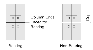
Bearing splices require that the mating faces be prepared or ‘Faced’ so that they make full contact over their entire surface area, by doing this, the loads are transferred in direct bearing. Facing is achieved by ‘saw-cutting’ the column to length, or in rare, extreme circumstances, by machining. The splice plates then effectively simply hold the two ends together making them smaller and easier to fabricate.
Non-Bearing splices ignore any direct bearing between the two members, relying on the splice plates and connecting bolts to transfer the load, this connection type generally requires a larger splice and tends to be more complex to analyze.
The non-bearing splice is usually discounted in favor of the bearing.
Typically, a column is spliced at every 3rd storey of the building – with a maximum length of 12 m. beyond 12 m becomes very difficult to transport and handle on site.
Slices should ideally be configured so that the ‘centroids’ of the column section/s are in-line.
Bolted Splices
In-Line Cap and End-Plates
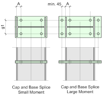
The simplest and most cost-effective splice is the cap and base-plate, it’s compact and neat and is ideal if the splice is subject to low moments and the joint can be located close as possible to a point of lateral restraint.
If a more significant moment resistance is required the cap and end-plates may be extended beyond the profile of the column providing for an additional set of bolts.
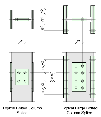
The bolts should be placed as close to the column flanges as reasonable - in this example, an M20 bolt should not be less than 45 mm, allowing for the wrench socket. Inside bolts (A) should work out the same, adding the flange thickness.
The bolt pitch (g1) should be in accordance with the Recommended Gauge
Offset Cap and End-Plate Splices
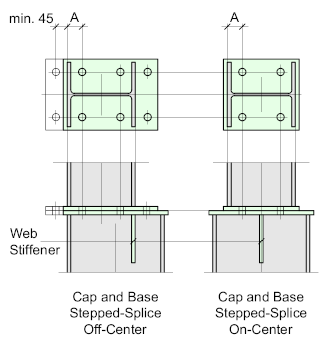
This configuration can also apply to offset, or stepped splices which connect columns of different sizes.
With offset connections, there is no continuous load path through the flanges, so it may be necessary to include stiffener welded into the web of the lower (larger) column. This stiffener should be continuous, that's to say a slot should be cut into the web and be fully welded after fitment.
If the offset is equal about the column centres and the size differential between the columns is not sufficient to accommodate the stiffener under the flanges, then it should be welded on the centre-lin of the column in the same manner.
Generally, the splice plate thicknesses should no be less than the thickness of the thicker flange, while the web stiffeners should not be less than the thickness of the thickest of the webs.
Flange and Web Plates
Splicing a column for larger moments usually requires the use of flange and web splice-plates forming the more conventional and recognizable configuration. In such connections, the column ends should be ‘faced’ so that the compressive load is transmitted by bearing.
There is a medium and heavy duty version of this splice. The medium duty requires two flange plates bolted to the outside of the column flanges and 2 web plates bolted each side of the web. This configuration is common for column sizes up to 250 mm. Larger columns will usually require a double set of flange plate bolted inside and outside of the flanges.
In both cases, the length of the splice and the number of bolts must be provided by the responsible engineer.
The Bolt Gauge (g1 and g2) should be in accordance with the recommended gauge for the given profiles and the Bolt Pitch should be that as for moment connections
Splicing In-Line Columns of Different Sections or Serial Size
Where two columns of a different serial-size or mass need to be spliced, it will be necessary to use a ‘stepped-splice’.
A ‘stepped’ splice requires the use of a division-plate in order to evenly transfer the compression forces by direct bearing – the division-plate is usually shop-welded to the cap of the lower section, while the base on the upper column is site-bolted to the division plate by means of angle-cleats or a base-plate.
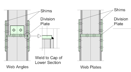
The stepped splice may be either In-Line or Offset. In both cases, sufficient packs must be provided to accommodate the differences in section sizes.
In all cases the column ends connecting to the division-plate must be faced for bearing.
Welded Splices
In almost every case a welded splice will be a shop-splice. It’s vitally important that the column is straight and continuous along its axis, any misalignment will affect the effective length and create a ‘weak-point’ to encourage buckling. As this is very difficult to achieve with on-site welding, it should be avoided.
Another reason to avoid site-welded splices, is that it can be difficult to hold the upper column length in position – the temporary web splice-plate will assist to some extent, but its real purpose is to hold the two faces together and not to stabilize the upper column length.
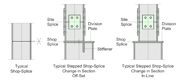
Welded splices work well where there is a change in section or serial size. In such cases a division-plate is shop-welded to the lower column cap, while a short stub-section of the upper column is welded to the plate. It’s then possible to fit a conventional bolted-splice to continue the column.
Such ‘stepped’ splices may be configured ‘In-Line’ or ‘Offset’ where the column faces must be in-line to accommodate an outside wall of sheeting.
Offset splices will require a stiffener welded into the web of the column – this stiffener should be continuous in that a slot should be cut into the column web with the stiffener fitted into the slot.

Very useful information thank you.
We will soon be adding column splices for hollow sections – so keep checking back
Very useful information thank you.
Could you explain me why the splices should be located on the point of small displacement?
My initial thought was that the high curvature( and not high displacement) would be worse, so the point of smaller Bending moment would be ideal.
Thanks.
There are two main reasons for placing the splice just above the floor level: Theoretically, the splice could be placed anywhere along the column length depending on how its designed, but generally, a splice should not be placed at the point of maximum deflection where it has to deal with lateral forces (Wind) – after all, it’s primarily a compression joint.
Secondly, placing it just above the floor level allows for a convenient platform for the erectors to make the joint without the need for additional suspension platforms.