Multi-Storey structures generally require that the columns be ‘spliced’ in order to extend their length for the full height of the structure. Splices may be either bolted or welded and its always assumed that welded splices are ‘shop-welded’ while bolted splices are ‘site-bolted’. It is possible to call for a site-welded splice, but making such a connection can be difficult, time consuming, and often risky, and as such should be avoided. Splices should be designed so that the column is effectively continuous and therefore should be able to transmit the full bearing load throughout its total length.
They must also resist any horizontal moments that may be incurred by lateral displacement, consequently, column splices are generally designed to be ‘moment-resisting’. The column splice should always be placed as close to a point of lateral restraint as possible, and away from points of maximum deflection.
Typical Examples
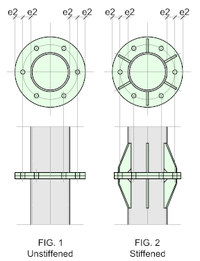
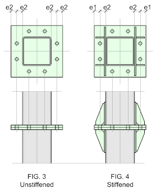
Column Splices - Cap and End-Plates
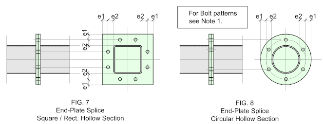
The cap and end-plate splice is probably the most widely used - it's straightforward to fabricate and erect and provided the column ends are faced for bearing and the column can be supported laterally close to the splice - it will fulfill most requirements. It will work for Circular, square and rectangular hollow section and may be stiffened or unstiffened,
Column Splices - Flange Plates
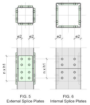
Using splice plates with hollow sections is slightly more complex and requires a high level of fabrication and erection accuracy.
for the most part the connection is made using blind fixings enabling the splice plates to be loose shop-bolted to one of the column ends (usually at the top) while the other end is fastened on site. The splice plates may be fitted externally as shown in Fig. 5 or internally as indicated in Fig. 6.
The column ends are usually faced for bearing allowing full contact between the column faces. Alternatively, there may be a gap between the ends, in which case the splice plates and bolts must be designed to to resist the axial loads.
This connection is ideal if the splice is to be discrete - but discretion comes at a cost, so always bear that in mind.
Beam Splices - End-Plates
Beam splices typically resist large Bending Moments and shear forces. Ideally, the splice should be located away from the point of maximum deflection.
Hollow section beam splices are not that common, usually they are applied to single storey, light duty, open structures. The usual practice is that if the beam is long enough to require a splice then an open section would be used.
Consequently, for the duties mentioned, an simple end-plate splice would be sufficient, which may be stiffened or unstiffened (See Cap and End-Plates). Splice plates may also be used, but this is rare and would only be used if there is an issue with the aesthetics- but there is a more widely used solution for these instances.
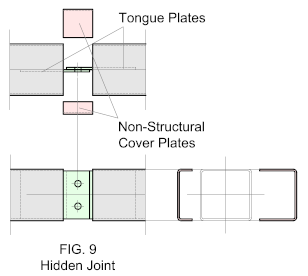
Hollow Section Hidded Splices.
In this example, the joint is made up from tongue-plates which are then 'hidden' by means of cover plates.
These are defined as non-structural and are formed by cutting a profile in half, wrapping around the joint. They are cut from a profile size matching that of the incoming beam.
They may be site welded after erection or alternatively, site bolted to tabs welded to the inside of the incoming beam profile. Either way, it's a lot of site work and should only be used at the discretion of the architect or engineer.
