Sometimes it’s necessary to join together two beams in order to extend its length, this may be necessary when the required beam length exceeds that which is commercially available, or for reasons of transportation and/or erection issues.

Beam splices typically resist large Bending Moments and shear forces and it is typically assumed that the flange splice carries the moment forces while the web splice carries the shear, Ideally, the splice should be located away from the point of maximum deflection. Where this is not possible, particularly in the case of heavy plate girders, it must be designed so that the web splice carries its share of the resultant moment.
Beam splices may be either welded or bolted, welded splices are generally considered to be shop welds, while bolted splices are generally considered to be ‘site’ splices.
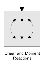
Site welded splices may be specified by the architect or engineer when considering the aesthetic properties of the joint, particularly in public buildings where the joint will be visible.
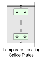
In such cases, it’s common practice to provide temporary bolted splice plates to hold the two pieces together, preferably as close to the weld as practical, such plates are then removed after the joint has been completed. However, site welded splices are never easy, due to the necessary tight tolerances involved and they are costly and time-consuming. Safety is also a major consideration as site-welding often requires temporary platforms to be supplied and installed at places in close proximity to the work to be done, so unless there are compelling reasons, they should be avoided.
It’s difficult to standardize splices, they are considered to be critical connections and must be properly designed taking into account the stress distribution, therefore, the following examples represent what are considered to be fairly typical:
Bolted Splices
Bolted splices are without doubt the most common and provided they have been shop fabricated to a high level of accuracy and located at a point where they can be easily and safely accessed they are relatively straightforward to fabricate and erect. It’s always a good idea to trial-assemble bolted splice joints in the workshop prior to delivery to site to ensure correct alignment and eliminate unpleasant surprises on site which can be difficult to impossible to fix in-situ.
Note! Bolted splices are never a good idea if the beam or girder is dynamically loaded, such as in Crane Gantry Girders, the discontinuity at the joint could lead to stress raisers in the connection precipitating fatigue failure in the plate.
Bolted splices often require the use of HSFG (High Strength Friction Grip) bolts, so the draftsman should study the design requirements carefully, or check with the responsible engineer. If they are required, then it must be clearly noted on the drawing and highlighted on the inspection report.
Bolted splices may be configured in a number of ways depending on the design requirements
Bolted Web Splice Joints
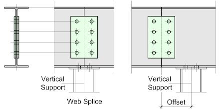
The Bolted Web-Splice is the simplest of all the beam splices, it’s used basically for joining two beams together and is usually situated immediately above, or close to a point of vertical support.
Such splices only connect to the beam web and consequently offer virtually no resistance to bending moments. The plates may be either double (as illustrated) or single, connecting to only one side of the web.
Bolted End-Plate Splice Joints
Bolted end-plate splice joints are invariably designed as moment resisting connections, with any shear resistance carried by the bolts. As a consequence, special attention must be paid to the plate thicknesses and the quality of the welding of the end plate to the tension flange, which invariably should be a full-penetration groove weld.
Such splice joints look fairly simple and straightforward but they require a high level of fabrication accuracy, the beam ends must be square and the end plates must be perfectly flat to ensure the non-slip connection, so attention must be given to the welding so as to avoid distortion of the end-plates.
High strength friction grip bolts are usually a requirement in such connections which should be pre-tensioned to give a non-slip connection.
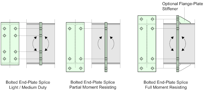
Generally, the first and last row of bolts at the joint should be as close as practical to the inside flanges of the connecting beams
- The light duty joint, where the bolts are located inside of the beam flanges, is used where the bending moments are modest. (See Detailing Notes)
- Where significant moment resistance is required the end-plate should extend beyond the tension flange.
- Where the joint is to be subjected to a full reversal of the moments, the end plate should extend beyond both flanges.
- End-Plate splice joints may also be used when splicing beams of different depths and sections, provided adequate stiffening is provided to the beam web of the larger section.
Rules-of-Thumb
- The thickness of the splice plates should be between 1 and 1.5 x the beam flange thickness
- The bolt-diameters should be M20 for beams up to a depth of 450 mm.
- For beams depths above this figure - M24 bolts should be considered.
Bolted Flange / Web Splice Joints
More common are splices designed to resist both bending moments and shear forces, which require the use of both flange and web plates.
Generally, with such splices, the flange plates would be designed to resist the bending moments, while the shear is taken up by the web-plate and bolts.
Splices, of course need to be properly designed taking into account the moment and shear resistance, but to simplify their selection during preliminary design it’s possible to divide them into 3 categories: Small Beam Splice – Large Beam or Girder Splice, and Large Girder Splice.
Rules-of-Thumb
- Small beam splice would include beams of up to 50 kg / meter unit length
- Large beam or girder splice would apply to beams between 50 and 100kg/m.
- Large Girder-Splice would apply to Plate-Girders over 100 kg/m.
The following illustrations indicate typical splice configurations for light, medium, and heavy-duty applications.
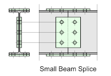
Small Beam Splice
Small beam splices typically comprise of two web plates and two flange plates bolted to the upper and lower faces of the flange.
Referring to the rule-of-thumb, they would typically be used for beams up to 50 kg/m unit length
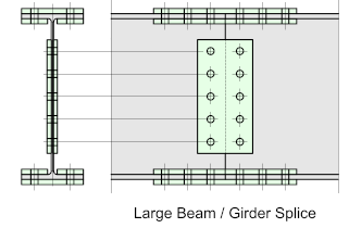
Large Beam Splice
Large beam splices typically comprise of web-plates bolted to each side of the beam web and double flange-plates effectively ‘sandwiching’ the beam or girder flanges.
Referring to the rule-of-thumb, they would typically apply to beams or girders within the range of 50 – 100 kg/m unit length
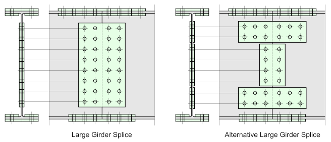
Large Girder Splice
Large girder-splices would typically comprise of web-plates bolted to each side of the beam web with a double row of bolts to resist the additional shear forces. In such connections Slip-Resistant’ bolts are commonly used.
The flange-plates, as above would be doubled.
Detailing Notes
Bolted Flange / Web splices are generally considered to be ‘site’ connections, consequently, the flange and web plates should be ‘loose-bolted’ to one end of the beam or girder for delivery to site, leaving the tightening or torqueing of the connection to the erection crew.
Where slip-resistant bolts are to be used for the web-plates they must be clearly identified and marked on the beam.
Rule-of-Thumb
- The flange plate thickness should not be less than the beam flange thickness
- The web-plate thickness should not be less than the beam web thickness
- Generally, when abutting the two beam-ends at the splice, they should be as close as possible, ideally not exceeding 3mm.
- Flange splice-plates should have a minimum of 8-bolts (4 each side)
- Web splice-plate should have a minimum of 4-bolts (2 each side)
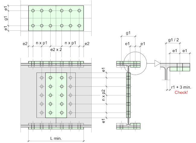
Typical Bolt Groups
Note!
Beam Splices are a safety-critical item, and as there are so many permutations they cannot be standardized. The tables below represent what is considered to be commonly accepted practice and should always be approved by the responsible engineer


How is bolting affected if the top flange is used as a rail to slid on (i.e. jack and slid operations to position objects over a hole). Effectively not allowing top rail to be bolted.
If I understand correctly you want to use the beam top flange as a skid – so a flange plate is not an option:
1. Can to support the beam from the underside using a post or corbel, or even a cross beam? – thereby using a web splice.
2. Can you move the splice? – but this can create more problems.
3- You could look at Crane Girders – for some ideas.
if you send me a sketch – I may have a more concrete suggestion.